
Warranty

044-05080 Rev. A 5-2
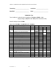
Table 5-2. Test Equipment Required
MENCLATURE MANUFACTURER MODEL
Signal Generator Agilent (H.P.) ESG4433B
30 dB Attenuator, 250 Watt Tenuline
Spectrum Analyzer H.P. 8562E
Coax Directional Coupler H.P. 778D
Power Meter / Sensor H.P. 437B / 8481A
Network Analyzer H.P. 8753D
Current Probe
Source Diskette Powerwave
5-4. PERFORMANCE TEST
Performance testing should be conducted every 12 months to ensure that the amplifier system
meets the operational specifications listed in table 5-3. Also verify system performance after any
amplifier module is replaced in the field. The test equipment required to perform the testing is listed
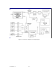
in table 5-2, and the test setup is shown in figure 5-1.
5-4.1. AMPLIFIER PERFORMANCE TEST.
To perform the test, proceed as follows:
1. Connect test equipment as shown in figure 5-1.
NOTE
Do not apply any RF signals at this time.
AMPLIFIER SPURIOUS EMISSIONS TEST:
2. Load the MFRM waveform on the ESG (signal generator). Apply this signal through a driver
amplifier to the MCPA so that the RF signal going into the MCPA is approximately -1.5
dBm (adjust the input RF signal level to get 48.5 dBm output power). Measure spurious
emissions. Verify that it is within specification.
GAIN TEST:
3. Set input power level to power amplifier at –1.5 dBm (869, 881, and 894 MHz).
4. Measure the output power in dBm.
5. Subtract input power (in dBm) from output power (in dBm) to get gain.
6. Check the amplifier gain across the band from 869 MHz to 894 MHz. Gain should be 50 ±2
dB. Record test data in table 5-3.
INPUT RETURN LOSS TEST:
7. Read and record the S
11
return loss measurement on network analyzer. Record test data in
table 5-3.