Draft RX 1850-1910 MHz; TX 1930-1945 MHz System Integration Manual Radio Frequency Front End Multi-Carrier Power Amplifier System 044-05082 Rev.
Draft RF Front End System Integraton Manual ® © 2001 Powerwave Technologies Incorporated. All rights reserved. Powerwave Technologies, and the Powerwave logo are registered trademarks Powerwave Technologies, Inc. reserves the right to make changes to the documentation and equipment, including but not limited to component substitution and circuitry changes. Changes that impact this manual may subsequently be incorporated in a later revision of this manual. March 2001 Powerwave Technologies, Inc. 1801 E.
DRAFT RF Front End System Integration Manual Section 1 General Discription 1-1 Introduction This manual contains information and procedures for installation, operation, and maintenance of the Radio Frequency Front End (RFFE) Multi-Carrier Power Amplifier (MCPA) System. This manual is organized into sections as follows: Section 1.General Description Section 2. Installation Section 3. Operating Instructions Section 4. Principles of Operation Section 5. Maintenance Section 6.
DRAFT RF Front End System Integration Manual 1-2.1.3 Masthead Unit Interface The Masthead Unit Interface (MHUI) interfaces the MHU to the host base station. It provides a user friendly control panel for power level adjustment and display. The control panel is key activated and displays major, critical and minor alarm conditions via LED displays. Refer to section 2 for a more detailed description of the MHUI controls.
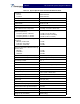
DRAFT RF Front End System Integration Manual Table 1-2 System Specifications with the MPA9505-55 MCPA Frequency: Receive Transmit 1850-1910 MHz 1930-1945 Mhz RF Input Power 3dBm (2 milliWatts) RF Output Power: 55 Watts (47.40 dBm) Max./ 7carriers Nominal Gain 40 dB ±1.0 dB Typical Gain Flatness ±0.2 dB (over any 2.0 MHz in band) Gain Variation Over Temperature 1.
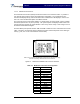
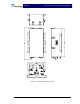
DRAFT RF Front End System Integration Manual Mounting Frame Transmit Module (typ. 2 plcs.) Common Box Figure 1-2 The Mast Head Unit with Two Transmit Modules 044-05082 Rev.
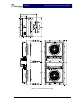
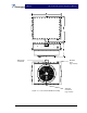
DRAFT RF Front End System Integration Manual Figure 1-3 Masthead Unit Assembly 044-05082 Rev.
DRAFT RF Front End System Integration Manual Figure 1-4 The Common Box Figure 1-5 Figure 1-6 The Common Box Assembly 044-05082 Rev.
DRAFT RF Front End System Integration Manual Blind-mate Connector Breather Vent. (Typ. 2 Plcs) Figure 1-7 The Transmit Module Assembly 044-05082 Rev. A 1-7 220 VAC Connector (Typ.
DRAFT RF Front End System Integration Manual Figure 1-8 Masthead Unit Interface Front and Rear Views. 044-05082 Rev.
DRAFT RF Front End System Integration Manual Section 2 Installation Instructions 2-1 Introduction This section contains unpacking, inspection, installation instructions and recommendations for the RF Front End (RFFE) System. It is important that the licensee perform the following tasks correctly and in good faith: 1. Carefully read all material in this section prior to equipment unpacking or installation. 2. Also, read and review the operating procedures in section 3 prior to installing the equipment. 3.
DRAFT RF Front End System Integration Manual 1. Visually inspect the MHU components and the MHUI for damage that may have occurred during shipment. 2. Check for evidence of water damage, bent or warped chassis, loose screws or nuts, or extraneous packing material in the connector(s). CAUTION Before applying power, make sure that all connectors to the Units are secure. Make sure that the input and output of the units are properly terminated at 50 ohms. Do not operate the system without a load attached.
DRAFT RF Front End System Integration Manual 4. Clamp the MHU frame to the antenna tower (see figure 1-4 for frame dimensions). 5. Place the common box into it’s location on the MHU frame (see fiqure 1-1). Secure in place with the supplied screws. 6. Place a transmit module on the MHU frame. Slide the module toward the common box until it locks into place with the blind mate connector on the common box. Tightened down with the supplied screws. 7. Repeat step 5 for the second transmit module. 8.
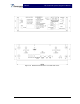
DRAFT RF Front End System Integration Manual Figure 2-1 DC IN, BATT1, BATT2 Terminal Board Layout Table 2-1 DC IN, BATT1, BATT2 Terminal Designations Terminal Point Designation No Polarity 27VDC No Polarity 27VDC RTN 2-7 MHU Power, Alarm, Control, and RF Connector 2-7.
DRAFT RF Front End System Integration Manual Table 2-3 MCPA Alarms & Controls Items Alarms & Controls Deletion Alarm Function Fail Alarm VSWR Alarm High Temp. Alarm Over Power Output Alarm DC Fail Alarm Loop Fail Alarm EN/DISABLE Specifications TTL Level; +5 Volts Buffer: 74ABT244 (5V) - recommended When unit does not exist (HEAR_PAU) Equipped: GND Deletion OPEN When unit does not exist (HEAR_PAU) Normal: High Abnormal GND 3:1 (6dB ± 1dB) @ 35dBm-48dBm Output Power.
DRAFT RF Front End System Integration Manual transmit lines with 120 ohms. Because this communications bus is also shared with other system resources, the MCPA supports the following asynchronous packet format communications protocol. The Low Speed Bus (LSB) 1 and 2 are selected by the following truth table: Table 2-5 The LSB 1 and LSB 2 Selection Truth Table 2-8.
DRAFT RF Front End System Integration Manual 2-9 Commands to the MHUI The CMND/ECHO byte is used to send commands from the host to the MHUI as follow: Table 2-8 CMND/ECHO comands from the Host to the MHUI Byte Command LEN=00H; CMND/ECHO= 00H Report base status 01H Enable HPA in MHU and report and report base status 02H Disable HPA in MHU and report base status 03H Report extended status 04H Interrogation of temperature in MHU at HPA heat sink 05H Interrogation of RF-output power at MHU HPA ou
DRAFT RF Front End System Integration Manual 2-9.1 Responses from the MHUI The MHUI responses always echo the received CMND byte as the ECHO byte of the response packet. Amplifier base status is reported by setting the LEN field to 01H and reporting the following bit mapped byte in the data field of the response packet for CMD==00h, 01h, 02h base status.
DRAFT RF Front End System Integration Manual Reply for commands 08H, 09H, 0BH and 0CH (data field): Cell size attenuator: 00H= full attenuation 20dB, FFH= no attenuation 0dB, step size 20/255 dB Cable normalization attenuator: 00H= full attenuation 20 dB, FFH= no attenuation 0dB, step size 20/255 dB For commands 12H and 13H the value in the data byte is defined in the same way as above for cell size and cable normalization respectively.
DRAFT RF Front End System Integration Manual J3 CONTROL J2b J1a RF OUT TO MHUI ANTENNA J2a To Rx/Tx Antenna J1b RF IN/OUT TO MHUI To Rx Diversity Antenna ANTENNA Battery Backup 1 Battery Backup 2 +27VDC Rx OUT ALARMS Rx DIVERSITY OUT RS-485 Tx IN HOST RADIO BASE STATION Figure 2-5 System Interconnect Diagram 044-05082 Rev.
DRAFT RF Front End System Integration Manual Section 3 Operating Instructions 3-1 Introduction This section contains operating instructions for Powerwave’s RF Front End system. 3-2 Location and Function of the MHU and MHUI Controls and Indicators The Masthead Unit (MHU) is not equipped with controls or indicators. Instead, the MHU interfaces with the host base station by way of the Masthead Unit Interface (MHUI). The location of the controls and indicators for the MHUI are shown in figure 3-1.
DRAFT RF Front End System Integration Manual 3-2.4 MHUI Cable-Normaliztion-Attenuators Settings/Cable-Normalization-Mode Selection Buttons The MHUI cable normalization attenuator setting is performed either manually or by remote control or by an automatic control algorithm. This is indicated by one of three LEDs illuminated.
DRAFT RF Front End System Integration Manual The alarm indicators show the instantaneous condition of the MHU and MHUI. 3-2.5.1 RF overpower • The MHU-MHUI-system waits 500ms, • then it will reduce the gain by 3 dB and then • makes 3 attempts to recover the gain at 500ms intervals without submitting an alarm via RS485 until (if not successful) it holds the current gain setting and reports an RF overpower shutdown. The unit will still be transmitting. 3-2.5.
DRAFT RF Front End System Integration Manual 3-3 Initial Start-Up and Operating Procedures To perform the initial start-up, proceed as follows: • Double check to ensure that all input and output cables are properly connected. CAUTION Before applying power, make sure that the input and output of the amplifiers are properly terminated at 50 ohms. Do not operate the amplifier without a load attached. Refer to Table 1-1 for input power requirements. Excessive input power may damage the MCPA.
DRAFT RF Front End System Integration Manual Section 4 Principles of Operations 4-1 Introduction This section contains a functional description of the Powerwave RFFE MCPA System. Refer to figure 4-1 and figure 4-3 for the system and amplifier functional block diagrams respectively. 4-2 RF INPUT Signal The maximum input power for all carrier frequencies should not exceed the limits specified in section 1, table 1-1 of this manual.
DRAFT RF Front End System Integration Manual single path configuration. Note that the splitter is not switched, therefore the power is automatically reduced by 3 dB, thus eliminating an output overdrive condition. The output of the combiner is fed through a coupler, then a receive-band filter. The amplified RF signal is available for use at the output of the receive-band filter (J2). The coupler is used to sample the output power to the true RMS detector.
DRAFT RF Front End System Integration Manual Main Section BLF2047s BLF2045s BLF2047s SYSTEM DRIVER (35dB) BLF2047s BLF2045s Driver Section BLF2047s RF-IN Combiner Section MRF284 MULTIFUNCTION BOARD PRE-D .125W 2W RF-OUT 30W BLF2045s AGC GAIN PHASE BLF2047s -30dB VSWR BLF2047s SAMPLE uProcessor BLF2047s BLF2045s BLF2047s VG3 VG2 VG1 OUTPUT DETECTOR Figure 4-2 MPA9505-55 MCPA Functional Block Diagram 4-4.
DRAFT RF Front End System Integration Manual Section 5 Maintenance 5-1 Introduction This section contains periodic maintenance and performance test procedures for the RF Front End (RFFE). It also contains a list of test equipment required to perform the identified tasks. NOTE Check your sales order and equipment warranty before attempting to service or repair the unit. Do not break the seals on the equipment under warranty or the warranty will be null and void.
DRAFT RF Front End System Integration Manual Table 5-2 Test Equipment Required Nomenclature Manufacturer Model 5-4 Clean Air Inlets/Outlets The air inlets and outlets should be cleaned every 30 days. If the equipment is operated in a severe dust environment, they should be cleaned more often as necessary. Turn off DC power source before removing fans. If dust and dirt are allowed to accumulate, the cooling efficiency may be diminished.
DRAFT RF Front End System Integration Manual 5-6 Field Replaceable Parts and Modules The following parts and modules can be replaced in the field on site by a qualified technician with experience maintaining RF power amplifiers and similar equipment: • • Transmit Modules Cooling Fans 5-6.1 Replacing a Transmit Module The To replace a power amplifier module, proceed as follows: 1. Turn off the 220 VAC circuit breaker that feeds the MHU 2.
RF Front End System Integration Manual Section 6 Troubleshooting 6-1 Introduction This section contains a list of problems which users have encountered and a few suggested actions that may correct the problem. If the suggested corrective action does not eliminate the problem, please contact your Powerwave field representative or the factory for further instructions. Note Check your sales order and equipment warranty before attempting to service or repair the unit.