
User Manual

G3S-800-140-031 Installation & Service Manual
Copyright Powerwave Technologies, Inc., September 2001. All rights reserved
044-05095 Rev. A 3-1 September 2001
Section 3 Operating Instructions
3-1 Introduction
This section contains operating instructions for the Multicarrier Cellular Amplifier System.
3-2 Location And Function Of Amplifier Module Controls And Indicators
Primary +27 Vdc power is applied to the amplifier via a 100-amp circuit breaker (ON-OFF) lo-
cated on the left side of the amplifier front panel.
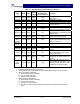
The plug-in amplifier module RF control and indicators, located in the center of the amplifier front
panel between the cooling fans, are shown in figure 3-1. The status and RF control functions and
alarms are described in detail in the subsequent paragraphs.
Figure 3-1 G3S-800-140-031 Amplifier Module RF Control and Indicators
3-2.1 Voltage Indicators And On/Off/Reset Switch
3-2.1.1 +27VDC Indicator
Green LED. When lit, indicates that the +27 Vdc supply is greater than +21 Vdc and less than
+31 Vdc. If the +27 Vdc indicator goes out, the DC FAIL indicator will illuminate. This indicates
that the +27 Vdc voltage dropped below +21 Vdc.
3-2.1.2 +15VDC Indicator
Green LED. When lit, indicates that the +15 Vdc supply is greater than +12 Vdc and less than
+17 Vdc. If the +15 Vdc indicator goes out, the DC FAIL indicator will illuminate. This indicates
that the +15 Vdc voltage dropped below +12 Vdc or increased above +17 Vdc.