
User Manual

G3S-800-140-031 Installation & Service Manual
Copyright Powerwave Technologies, Inc., September 2001. All rights reserved
044-05095 Rev. A 2-1 September 2001
Section 2 Installation
2-1 Introduction
This section contains installation recommendations, unpacking, inspection, and installation in-
structions for the Multicarrier Cellular Amplifier. Carefully read all material in this section prior to
equipment unpacking or installation. Also read and review the operating procedures in Section 3
prior to installing the equipment. It is important that the licensee perform these tasks correctly
and in good faith. If applicable, carefully review the Federal Communications Commission (FCC)
rules as they apply to your installation. DON'T TAKE CHANCES WITH YOUR LICENSE.
2-2 Electrical Service Recommendations
Powerwave Technologies recommends that proper AC line conditioning and surge suppression
be provided on the primary AC input to the +27 Vdc power source. All electrical service should
be installed in accordance with the National Electrical Code, any applicable state or local codes,
and good engineering practice. Special consideration should be given to lightning protection of
all systems in view of the vulnerability of most transmitter sites to lightning. Lightning arrestors
are recommended in the service entrance. Straight, short ground runs are recommended. The
electrical service must be well grounded.
Each amplifier system should have its own circuit breaker, so a failure in one does not shut off
the whole installation. Circuit breakers should be capable of handling the anticipated inrush cur-
rent (normally 25% over equipment maximum current draw), in a load center with a master
switch. A 70-amp circuit breaker installed in the power distribution unit is recommended for each
amplifier. Either 2 or 4 AWG DC wire should be installed for each amplifier based on the cable
design and length.
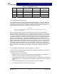
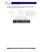
Table 2-1 Averaged Current
Amplifier
Power
No. Of
Amplifiers
3 Sector
Averaged Current
2 Sector
Averaged Current
1 Sector
Averaged Current
140 12 588
140 9 441 504
140 6 294 336 378
140 1 49 56 63
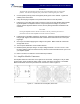
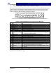
2-3 Air Conditioning
Each G3S-800-140-031 amplifier generates 5971 BTUs of heat at full power. A fully populated
MCR30829-1-3 subrack operating at full power will generate 17,913 BTUs of heat. A full three-
sector site employing three fully populated MCR30829-1-3 subracks will generate 53,739 BTUs
of heat at full power (360W per subrack). A five-ton air conditioner is needed to cool this Power-
wave equipment. A full three-sector site probably needs at least a five-ton air conditioner to cool
all of the site's equipment, based on heat load averaging as described in table 2-2. Since all the
amplifiers are not running at full capacity at the same time in normal operation, table 2-2 de-
scribes the heat load for a 3 sector (70%), 2 sector (80%) and omni (90%) site. Perform a site
survey to determine actual air conditioning needs.