
User Manual

G3S-800-140-031 Installation & Service Manual
Copyright Powerwave Technologies, Inc., September 2001. All rights reserved
044-05095 Rev. A 2-3 September 2001
WARNING
Verify that all circuit breaker switches on the power distribution panel are in the OFF
position. Turn off external primary DC power before connecting DC power cables.
5. Connect positive primary power and negative primary power to the subrack. Tighten the
subrack power connections.
6. Verify that the plug-in amplifier’s front panel On/Off switch is in the Off position.
7. Inspect the 21-pin D-Sub male combo connector on the rear of each amplifier before install-
ing the amplifier in the amplifier subrack. Verify that all pins are straight, no pins are re-
cessed, that the alignment shield is not bent, and no packing material is embedded in the
connector.
CAUTION
Forcing the amplifier into the subrack at too fast a rate may cause the pins on the 21-
pin D-sub connector of the amplifier to become recessed or broken.
8. Install the plug-in amplifier module(s) in the subrack. Tighten left and right thumbscrews un-
til finger tight. Tighten the thumbscrews with a slotted screw driver about 1/8 of a turn past
finger tight.
9. Check your work before applying DC voltage to the system. Make certain all connections
are tight and correct.
10. Turn the power distribution circuit breakers back on.
11. Measure primary DC input voltage. DC input voltage should be +27 Vdc ±1.0 Vdc. If the
DC input voltage is above or below the limits, call and consult Powerwave before you turn on
your amplifier system.
12. Refer to section 3 for initial turn-on and checkout procedures.
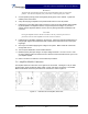
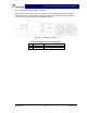
2-6 Amplifier Module Connectors
The amplifier has three connectors on the right rear of the module. The larger is a 21-pin male
D-Sub combo, which provides the status, alarm, control, and power connections. The smaller
BMA coaxial female connectors provide the RF connections. Refer to figure 2-1.
Figure 2-1 G3S-800-140-031 Amplifier, Rear View