869-894 MHz Installation & Service Manual Model SCA 9350-30 Single-Channel Cellular Amplifier Copyright Powerwave Technologies, Inc., December 2001. All rights reserved 044-xxxxx Rev.
SCA 9350-30 Installation and Service Manual © 2001 Powerwave Technologies Incorporated. All rights reserved. Powerwave Technologies, and the Powerwave logo are registered trademarks Powerwave Technologies, Inc. reserves the right to make changes to the documentation and equipment, including but not limited to component substitution and circuitry changes. Changes that impact this manual may subsequently be incorporated in a later revision of this manual. December 2001 Powerwave Technologies, Inc.
SCA 9350-30 Installation and Service Manual Table Of Contents Section 1 General Description Par. No. 1-1 1-2 1-3 1-4 Page No. Introduction ................................................................................................................................... 1-1 General Description....................................................................................................................... 1-1 Functional and Physical Specifications ...................................................
SCA 9350-30 Installation and Service Manual Section 6 Troubleshooting 6-1 6-2 6-3 6-3.1 6-3.2 Introduction ................................................................................................................................... 6-1 Trouble shooting............................................................................................................................ 6-1 Return for Service Procedures.............................................................................................
SCA 9350-30 Installation and Service Manual Section 1 General Description 1-1 Introduction This manual contains information and procedures for installation, operation, and maintenance of Powerwave’s SCA 9350-30 (Nortel Model No. NTQA37AA) single-channel cellular amplifier. The manual is organized into six sections as follows: Section 1. General Description Section 2. Installation Section 3. Operating Instructions Section 4. Principles of Operation Section 5. Maintenance Section 6.
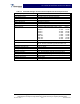
SCA 9350-30 Installation and Service Manual Table 1-1 SCA 9350-30 Single-Channel Cellular Amplifier Functional Specifications Frequency Range Nominal Input Power Total Output Power RF Gain at 1960 MHz Gain Variation Over All Conditions: Output Protection: Input Port Return Loss: Out of Band Spurious: Spectral Mask Duty Cycle: DC Input Power: Heat Dissipation Operating Temperature: Storage Temperature: Operating Humidity: Storage Humidity: RF Input / Output Connector DC Power Connector Data I/O Connector D
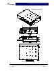
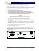
SCA 9350-30 Installation and Service Manual All dimensions are in inches And are for reference only Figure 1-1. SCA 9350-30 Amplifier Copyright Powerwave Technologies, Inc., December 2001. All rights reserved All specifications are subject to change without notice. Contact the factory for complete performance data. 044-xxxxx Rev.
SCA 9350-30 Installation and Service Manual Section 2 Installation 2-1 Introduction This section contains installation recommendations, unpacking, inspection, and installation instructions for the SCA 9350-30 single channel cellular amplifier. Carefully read all material in this section prior to equipment unpacking or installation. Also read and review the operating procedures in Section 3 prior to installing the equipment. It is important that the licensee perform these tasks correctly and in good faith.
SCA 9350-30 Installation and Service Manual 2-4 Installation Instructions (Refer to figures 1-1 and 2-1) The SCA 9350-30 is intended for installation in a Restricted Access Location. The SCA 9350-30 amplifier module is designed for installation in a subrack that permits access to the amplifier’s front panel for connection of DC power, RF, and monitor cables. To install the amplifier proceed as follows: 1. Install amplifier in the BTS rack and secure in place. 2.
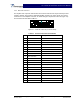
SCA 9350-30 Installation and Service Manual 2-5.1 Data I/O Connector The amplifier has a separate remote alarm and control connector that may be used by the host system to monitor and control the individual amplifier modules. The status, alarm, and control connections on the amplifier connector are made through a 20-pin SCSI connector (figure 2-2) and are listed and described in table 2-1.
SCA 9350-30 Installation and Service Manual 2-5.2 Amplifier RF Connectors The amplifier has two RF connectors. The RF Input connector is a SMA female. The input power on this port should not exceed the level specified in table 1-1. The RF Output connector is Type N female. They are listed and described in table 2-2. Table 2-2 Amplifier RF Connector Definition Function Description RF Input SMA Female RF Output Type N Female 2-5.
SCA 9350-30 Installation and Service Manual Section 3 Operating Instructions 3-1 Introduction This section contains operating instructions for the single channel cellular amplifier system. 3-2 Location And Function Of Amplifier Indicators The front panel LED is located to the right of the 20-pin Data connector and indicates the amplifier status. • Green means the amplifier is operating properly. • Red indicates an alarm or off condition.
SCA 9350-30 Installation and Service Manual Section 4 Principles of Operation 4-1 Introduction This section contains a functional description of the single-carrier SCA 9350-30 amplifier. 4-2 RF Input Signal The maximum input power should not exceed the levels to produce the maximum rated RF output power in table 1-1. This level is approximately 0 dBm, but should be set through the basetransceiver station’s software interface. See the BTS manual for detailed instructions.
SCA 9350-30 Installation and Service Manual 4-4.1 Driver Amplifier The driver amplifier is a two-stage amplifier which provides approximately 28 dB of gain in the 25 MHz frequency band from 869 to 894 MHz. The amplifier is mounted directly on a heat sink, which is temperature monitored by a thermal sensor. 4-4.2 Main Amplifier The main amplifier is a single-stage Class AB amplifier with approximately 13 dB gain and a P1dB of +50 dBm. The amplifier’s output is protected from output mismatches.
SCA 9350-30 Installation and Service Manual Section 5 Maintenance 5-1 Introduction The amplifier is designed to be operated without any required periodic maintenance other than maintenance which may be recommended by the manufacturer of the BTS. Please consult your BTS manual for guidance. Copyright Powerwave Technologies, Inc., December 2001. All rights reserved 044-xxxxx Rev.
SCA 9350-30 Installation and Service Manual Section 6 Troubleshooting 6-1 Introduction This section contains a list of problems and a few suggested actions that may correct the problem. If the suggested corrective action does not eliminate the problem, please contact your Powerwave field representative or the factory for further instructions. NOTE Check your sales order and equipment warranty before attempting to service or repair the unit.