
User's Manual
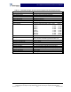
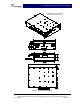
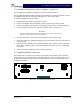
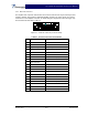
Table Of Contents

SCA 9350-30 Installation and Service Manual
Copyright Powerwave Technologies, Inc., December 2001. All rights reserved
044-xxxxx Rev. x 2-3 December 2001
2-5.1 Data I/O Connector
The amplifier has a separate remote alarm and control connector that may be used by the host
system to monitor and control the individual amplifier modules. The status, alarm, and control
connections on the amplifier connector are made through a 20-pin SCSI connector (figure 2-2)
and are listed and described in table 2-1.
Figure 2-2 Data I/O Connector (on Front Panel)
Table 2-1 Data I/O Connector Pin Definition
Pin Function Description
1 Ground Ground
2 Ground Ground
3 Synchro Signal + Synchro Signal from TRX
4 UART TX + Information Exchange (TRX to PA)
5 Manual Control To Set PA in Test Mode
6 Not Connected
7 UART RX + Information Exchange (PA to TRX)
8 Not Connected
9 Not Connected
10 Not Connected
11 Ground Ground
12 Ground Ground
13 Synchro Signal - Synchro Signal from TRX
14 UART TX - Information Exchange (TRX to PA)
15 Not Connected
16 Not Connected
17 UART RX - Information Exchange (PA to TRX)
18 Not Connected
19 Not Connected
20 Not Connected