
User's Manual
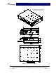
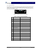
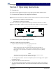
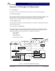
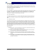
Table Of Contents

SCA 9350-30 Installation and Service Manual
Copyright Powerwave Technologies, Inc., December 2001. All rights reserved
044-xxxxx Rev.x 4-1 December 2001
Section 4 Principles of Operation
4-1 Introduction
This section contains a functional description of the single-carrier SCA 9350-30 amplifier.
4-2 RF Input Signal
The maximum input power should not exceed the levels to produce the maximum rated RF output
power in table 1-1. This level is approximately 0 dBm, but should be set through the base-
transceiver station’s software interface. See the BTS manual for detailed instructions.
4-3 RF Output Load
The load impedance should be as good as possible (1.5:1 or better) in the working band for good
power transfer to the load.
4-4 SCA 9350-30 Amplifier
The amplifier, figure 4-1, has an average output power of 30 watts, and is designed to support
transmission in GMSK and EDGE modulation. With an input signal of approximately 0 dBm, the
amplifier will operate at its rated output power. The amplifier is comprised of:
Driver Amplifier
Main Amplifier
Multifunction Board
DC/DC Converter Module
Main Amp
Temp Sense
Det
Driver
DAC
MCU
RS-485 Intfc
20-pin SCSI
3
PWR Conn
Red/
Grn
Input Filter/
Protection
Current Sense
DC/DC
-48/+26
5 V Reg.
Power Supply
+26
Multifunction
Figure 4-1 SCA 9350-30 Amplifier Block Diagram