
User's Manual
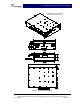
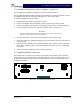
Table Of Contents

SCA 9350-30 Installation and Service Manual
Copyright Powerwave Technologies, Inc., December 2001. All rights reserved
044-xxxxx Rev. x 2-2 December 2001
2-4 Installation Instructions (Refer to figures 1-1 and 2-1)
The SCA 9350-30 is intended for installation in a Restricted Access Location.
The SCA 9350-30 amplifier module is designed for installation in a subrack that permits access to
the amplifier’s front panel for connection of DC power, RF, and monitor cables.
To install the amplifier proceed as follows:
1. Install amplifier in the BTS rack and secure in place.
2. Connect the amplifier front panel RF Out (Type-N) connector to the antenna cable.
3. Connect the amplifier front panel RF In (Type-SMA) connector to the transceiver output(s).
4. Connect the BTS 20-pin Data I/O cable to the amplifier. Refer to section 2-5.1.
WARNING
Turn off external DC power before connecting DC power cables. Verify that the
amplifier is terminated into a proper 50 Ohm load.
5. Connect the DC power cable to the rack and amplifier. Refer to section 2-5.3.
6. Check your work before applying DC voltage to the system. Make certain all connections are
tight and correct.
7. Measure DC input voltage. DC input voltage should be -36 to –60 VDC. If the DC input volt-
age is above or below the limits, call and consult Powerwave before you turn on your ampli-
fier system.
8. Refer to section 3 for initial turn-on and checkout procedures.
2-5 Amplifier Module Connectors
The amplifier has four connectors on the front of the module. These include a SCSI connector
which provides the data I/O connections, SMA female RF input, Type N female RF output, and 3-
pin high current contact DC input connectors. Refer to figure 2-1. Each is fully described in the
paragraphs that follow.
Figure 2-1 SCA 9350-30 Front Panel View