® INSTALLATION & SERVICE MANUAL MULTICHANNEL POWER AMPLIFIER NTGY81AC 1930-1990 MHz 50 WATTS AVERAGE POWER 04 April 2002 Powerwave Technologies, Inc. 1801 E. St. Andrew Place Santa Ana, CA 92705 044-xxxxx Rev. x Tel: (714) 466-1000 Fax: (714) 466-5800 Web Site: www.powerwave.
TABLE OF CONTENTS Par. No. 1-1 1-2 1-3 Section 1 General Description Page No. Introduction..................................................................................................................... 1-1 General Description....................................................................................................... 1-1 Functional and Physical Specifications...........................................................................
TABLE OF CONTENTS (Continued) Par. No. 5-1 5-2 5-3 5-4 5-4.1 5-5 Section 5 Maintenance Page No. Introduction..................................................................................................................... 5-1 Periodic Maintenance ..................................................................................................... 5-1 Test Equipment Required For Test ................................................................................ 5-1 Performance Test..................
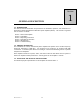
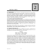
Section GENERAL DESCRIPTION 1 1-1. INTRODUCTION This manual contains information and procedures for installation, operation, and maintenance of Powerwave’s model NTGY81AC multichannel power amplifier (MCPA). The manual is organized into six sections as follows: Section 1. General Description Section 2. Installation Section 3. Operating Instructions Section 4. Principles of Operation Section 5. Maintenance Section 6: Troubleshooting 1-2.
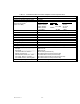
Table 1-1.
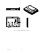
P1 P4 P5 P3 P2 RF OUT RF IN Figure 1-1. NTGY81AC Multichannel Power Amplifier 044-xxxxx Rev.
Section 2 INSTALLATION 2-1. INTRODUCTION This section contains unpacking, inspection, and installation instructions and recommendations for the Model NTGY81AC Multi Channel Power Amplifier. Carefully read all material in this section prior to equipment unpacking or installation. Also read and review the operating procedures in Section 3 prior to installing the equipment. It is important that the licensee perform these tasks correctly and in good faith.
2-4. INSTALLATION INSTRUCTIONS (Refer to figure 1-1) The NTGY81AC amplifier module is designed for installation on a heatsink that permits access to the module for connection of RF cables and the power, alarm, and control connector. To install the amplifier proceed as follows: 1. Install amplifier on heatsink with thermally conductive material inserted between amplifier module and heatsink, and secure in place with appropriate mounting screws. 2. Connect the antenna cable to RF OUT female SMA connector. 3.
2-6. ALARMS AND SENSING CONNECTOR P2 The alarms and sensing connections on the amplifier are made through a 14-pin micro-fit connector (figure 2-2) and are listed and described in table 2-2. Figure 2-2. Alarms and Sensing Connector P2 Table 2-2.
2-7. DIFFERENTIAL IIC CLOCK, RECEIVE, AND TRANSMIT CONNECTOR P3 The alarms and sensing connections on the amplifier are made through a 6-pin micro-fit connector (figure 2-3) and are listed and described in table 2-3. Figure 2-3. Differential IIC Clock, Receive, and Transmit Connector P3 Table 2-3.
Table 2-4. IIC, Power, Alarms, and Controls Connector P4 Definition PIN SIGNAL 1 +26_FAN 2 +26_FAN_RTN 3 FAN_ALARM1 4 FAN_ALARM2 5 FAN_ALARM3 6 AUX_ALARM+ 7 AUX_ALARM- 8 AUX_CTRL1 9 AUX_CTRL2 10 +5V_AIM_RTN 11 +5V_AIM 12 IIC_CLK+ DESCRIPTION 26V supply to the fans; routed from 12-position HPCA connector 26V supply returnto the fans; routed from 12-position HPCA connector Alarm for one of three fans in fan assembly / AIM.
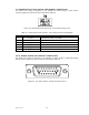
2-9. IIC, RS485, POWER, AND OTHER SIGNALS CONNECTOR P5 The alarms and sensing connections on the amplifier are made through a 18-pin micro-fit connector (figure 2-5) and are listed and described in table 2-5. Figure 2-5. IIC, RS485, Power, and Other Signals Connector P5 Table 2-5.
Section OPERATING INSTRUCTIONS 3 3-1. INTRODUCTION This section contains operating instructions for the Multicarrier Cellular Amplifier. 3-2. INITIAL START-UP AND OPERATING PROCEDURES There are no operating controls or indicators on the NTGY81AC amplifier module. To perform the initial start-up, proceed as follows: 1. Double check to ensure that all input and output cables are properly connected.
Section PRINCIPLES OF OPERATION 4 4-1. INTRODUCTION This section contains a functional description of the multichannel power amplifier (MCPA). 4-2. RF INPUT SIGNAL The maximum input power should not exceed the limits specified in table 1-1. 4-3. RF OUTPUT LOAD The load impedance should be as good as possible (1.5:1 or better) in the working band for good power transfer to the load. 4-4.
4-4.3. DRIVER AMPLIFIER The driver amplifier consists of two stages of class AB amplification which provide approximately 40 dB of gain in the 60 MHz frequency band from 1930 MHz to 1990 MHz. The amplifier operates on +26 Vdc, and a safe bias voltage which is controlled by microprocessors. 4-4.4. MAIN AMPLIFIER The main amplifier employs two class AB amplification stages for maximum efficiency. It provides approximately 25 dB of gain in the 60 MHz frequency band.
Section 5 MAINTENANCE 5-1. INTRODUCTION This section contains periodic maintenance and performance test procedures for the multichannel power amplifier. It also contains a list of test equipment required to perform the identified tasks. NOTE Check your sales order and equipment warranty before attempting to service or repair the unit. Do not break the seals on equipment under warranty or the warranty will be null and void.
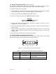
Table 5-2. Test Equipment Required MENCLATURE Signal Generator 30 dB Attenuator, 250 Watt Spectrum Analyzer Coax Directional Coupler Power Meter / Sensor Network Analyzer Current Probe Source Diskette Driver PA (1930-1990 MHz) MANUFACTURER Agilent (H.P.) Tenuline H.P. H.P. H.P. H.P. MODEL ESG4433B 8562E 778D 437B / 8481A 8753D Powerwave 12 dB gain, P1dB = 29 dBm (min) 5-4.
Figure 5-1. NTGY81AC Amplifier Test Setup Diagram 044-xxxxx Rev.
Table 5-3. Multichannel Power Amplifier NTGY81AC Test Data Sheet Tested By: ___________________ Serial No: ________________ Pass/Fail: ____________________ Date: ____________________ 50W MCPA Test Test Conditions: Load and source impedance: 50 ohms, VSWR < 1.2:1 Supply voltage: +26 Vdc ± 0.4 Vdc (unless otherwise noted). Network Analyzer Span: 60 MHz Marker #1 = 1930 MHz, #2 = 1960 MHz, #3 = 1990 MHz CONDITION TEST 1.00 1.01 NETWORK ANALYZER Gain 1.02 Gain Flatness 1.03 1.04 2.
5-5. FIELD REPLACEMENT OF THE MODULE The NTGY81AC multichannel power amplifier module can be replaced in the field on site by a qualified technician with adequate ESD protection and experience maintaining RF power amplifiers and similar equipment. To replace a power amplifier module, proceed as follows: 1. Turn off 26 Vdc power to that specific module. 2. Disconnect the two RF cables and connectors P1 through P5. 3. Remove 13 screws that secure amplifier module to heat sink. 4.
Section 6 TROUBLESHOOTING 6-1 INTRODUCTION This section contains a list of problems which users have encountered and a few suggested actions that may correct the problem. If the suggested corrective action does not eliminate the problem, please contact your Powerwave field representative or the factory for further instructions. NOTE Check your sales order and equipment warranty before attempting to service or repair the unit.