
User's Manual
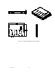
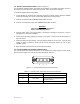
Table Of Contents

044-xxxxx Rev. x
iii
TABLE OF CONTENTS (Continued)
Par. Section 5 Page
No. Maintenance No.
5-1 Introduction..................................................................................................................... 5-1
5-2 Periodic Maintenance ..................................................................................................... 5-1
5-3 Test Equipment Required For Test ................................................................................ 5-1
5-4 Performance Test........................................................................................................... 5-2
5-4.1 Amplifier Performance Test............................................................................................ 5-2
5-5 Field Replacement of the Module................................................................................... 5-5
Section 6
Troubleshooting
6-1 Introduction.......................................................................................................................6-1
6-2 Troubleshooting................................................................................................................6-1
6-3 Return for Service Procedures .........................................................................................6-1
6-3.1 Obtaining an RMA ............................................................................................................6-1
6-3.2 Repackaging for Shipment ...............................................................................................6-1
LIST OF ILLUSTRATIONS
Figure Page
No. No.
1-1 NTGY81AC Multichannel Power Amplifier ..................................................................... 1-3
2-1 +26 Vdc Power and Ground Connector P1 .................................................................... 2-2
2-2 Alarms and Sensing Connector P2 ................................................................................ 2-3
2-3 Differential IIC Clock, Receive, and Transmit Connector P3.......................................... 2-4
2-4 IIC, Power, Alarms, and Controls Connector P4 ............................................................ 2-4
2-5 IIC, RS485, Power and Other Connector P5.................................................................. 2-6
4-1 NTGY81AC Multichannel Power Amplifier Functional Block Diagram ........................... 4-2
5-1 NTGY81AC Amplifier Test Setup Diagram .................................................................... 5-3
LIST OF TABLES
Table Page
No. No.
1-1 NTGY81AC Multichannel Power Amplifier Functional Specifications..... ....................... 1-2
2-1 +26 Vdc Power and Ground Connector P1 Definition .................................................... 2-2
2-2 Alarms and Sensing Connector P2 Definition ................................................................ 2-3
2-3 Differential IIC Clock, Receive, and Transmit Connector P3 Definition.......................... 2-4
2-4 IIC, Power, Alarms, and Controls Connector P4 Definition ............................................ 2-5
2-5 IIC, RS485, Power and Other Connector P5 Definition.................................................. 2-6
5-1 Periodic Maintenance ..................................................................................................... 5-1
5-2 Test Equipment Required............................................................................................... 5-2
5-3 Multichannel Power Amplifier NTGY81AC Test Data Sheet .......................................... 5-4
6-1 Troubleshooting..............................................................................................................6-1