
User Manual

G3L-1900-31/G3L-1900-31-A Operation Manual
Ó Copyright Powerwave Technologies, Inc., June 2002. All rights reserved
All specifications are subject to change without notice. Contact the factory for complete performance data.
044-05116 Rev. A
A-1 June 2002
Appendix A. Specifications
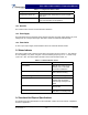
Table A-1 G3L-1900-31/31-A Wideband Multicarrier Cellular Amplifier Functional
Specifications
Frequency Range 1930 - 1990 MHz (60 MHz Bandwidth)
Instantaneous Bandwidth 20 MHz *
Total Typical / Maximum Input Power -15.6 - +4.9 / +5.9 dBm
Total Output Power 31 W (44.9 dBm)
Adjacent Channel Leakage Power
Ratio (ACLR) Spectrum Analyzer set-
tings: 30 KHz RBW, 300 KHz VBW,
True RMS detector
ACLR1 <-46dBc@f=fc ±5 MHz
ACLR2 <-51dBc@f=fc ±10 MHz
RF Gain 40 dB +0.5 dB
Gain Flatness:
±0.5 dB
Output Protection: Mismatch Protected
Input Port Return Loss: 18 dB min
Harmonics: Better than -50 dBc
Out of Band Spurious: Better than -60 dBc
Duty Cycle: Continuous
DC Input Power:
G3L-1900-31
-48 Vdc nominal, 9.1 amps typical (15 amps max)
Operational -57 Vdc to -60 Vdc (Po derated outside
normal operating range)
AC Input Power:
G3L-1900-31-A
230 Vac nominal, 1.9 amps typical (3 amps max)
Operational 264 Vac to 300 Vac (Po derated outside
normal operating range)
Operating Temperature: -10 ºC to +50 ºC
Storage Temperature: -40 ºC to +85 ºC
Operating Humidity: 0 % to 80 % Relative Humidity (noncondensing)
Storage Humidity: 0 % to 100 % Relative Humidity (noncondensing)
AC, DC Input, Summary Alarm, Base
Station Communication TLCI Bus:
Elcon Modular Flatpaq
tm
RF Input Connector: SMA Female
RF Output Connector: Type N-Female
Power Consumption: 435 Watts @ P
o
= 31 W average power
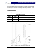
Weight: 28 lbs.
Dimensions: 3.125” High, 16.75” Wide, 14.125” Deep, 15.75” Deep
including connector guides
* The command received from the base station includes the operating band and based on that
band, the pilot frequency sets to 10 MHz lower than the lowest carrier in the operating band.