
User Manual
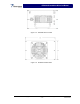
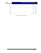


Table Of Contents

SPA9329-35 Installation & Service Manual
2-4 Installation Instructions
The SPA9329-35 booster amplifier module is designed for installation in an enclosure that
permits access to the front of the module for connection of the RF cables and the power connec-
tors.
WARNING
Turn external primary DC power off before connecting any cables.
1. Connect the +27 VDC power source to the booster power input connector (see figures 2-1,
3-1, and table 2-1). Do not apply power at this time.
2. Connect the RF input cable to the RF IN connector.
3. Connect the RF output cable to the RF OUT connector.
4. Refer to section 3 for initial turn-on and checkout procedures.
2-5 +27 VDC Power & Ground Connector
The +27 Vdc power and ground connections on the amplifier are made through a 3-pin female D-
Sub connector (figure 2-1) and are listed and described in table 2-1.
3 2 1
Figure 2-1 +27 Vdc Power & Ground Connector
Table 2-1 +27 Vdc Power & Ground Connector Descriptions
Pin Signal Description
1 Open
2 +27V +27 Vdc
3 RTN +27 Vdc return
Copyright Powerwave Technologies, Inc., October 2002. All rights reserved
2-2 October 2002