
User Manual
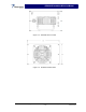
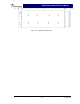


Table Of Contents

SPA9329-35 Installation & Service Manual
Section 3 Operating Instructions
3-1 Introduction
This section contains operating instructions for the SPA9329-35 power booster amplifier.
3-2 Initial Start-Up & Operating Procedures
Operating controls, indicators, and connectors located on the SPA9329-35 booster amplifier
module are listed in table 3-1 and corresponding locations for each are shown in figure 3-1. To
perform the initial start-up, proceed as follows:
1. Verify that all power and RF input and output cables are properly connected, per section 2.
CAUTION
Before applying power, make sure that the input and output of the amplifier are prop-
erly terminated at 50 ohms. Do not operate the amplifier without a load attached. Re-
fer to table 1-2 for input power requirements. Excessive input power may damage the
amplifier.
NOTE
The output coaxial cable between the amplifier and the antenna must be 50-ohm co-
axial cable. Use of any other cable will distort the output.
2. Turn on supply that provides +27 Vdc to the amplifier system.
3. Set the DC power ON–OFF switch to ON. The corresponding PWR and TMP LED indicators
should illuminate.
4. Apply the RF input signal.
Table 3-1 SPA9329-35 Controls, Indicators, and Connectors
Function Description
RF IN RF channel input connector
RF OUT RF output connector
PWR IN +27 VDC power input connector
ON–OFF ON–OFF switch. Applies DC power to channel
amplifier
PWR LED indicator – Illuminates when correspond-
ing ON–OFF switch is set to ON
TMP LED indicator – Illuminates when correspond-
ing ON–OFF switch is set to ON. Goes out if
amplifier overheats or VSWR is high.
Copyright Powerwave Technologies, Inc., October 2002. All rights reserved
3-1 October 2002