
User's Manual

SPA9323-30C Installation & Service Manual
© Copyright Powerwave Technologies, Inc., October 2004. All rights reserved
044-05178 Rev. A 3-1 October 2004
Section 3 Operating Instructions
3-1 Introduction
This section contains operating instructions for the single channel cellular amplifier system.
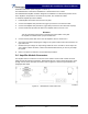
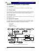
3-2 Location And Function Of Amplifier Indicators
The front panel LED, located to the right of the 20-pin data connector, indicates the amplifier
status.
• Green indicates the amplifier is operating properly.
• Red indicates an alarm or off condition.
The nature of the alarm can only be determined through the software interface of the Base-
Transceiver System (BTS). Please consult the BTS manual for details on monitoring amplifier
status.
Figure 3-1 Front Panel Indicators
3-3 Initial Start-Up And Operating Procedures
To perform the initial start-up, proceed as follows:
1. Verify that all input and output cables are properly connected.
CAUTION
Before applying power, make sure that the input and output of the amplifier
are properly terminated at 50 ohms. Do not operate the amplifier without a
load attached. Refer to table 1-1 for input power requirements. Excessive
input power may damage the amplifier.
NOTE
The output coaxial cable between the amplifier and the antenna must be 50-
ohm coaxial cable. Use of any other cable will distort the output.
2. Turn on supply that provides -48 Vdc to the amplifier system. Do not apply an RF signal to
the amplifier system
3. Verify that the LED is lit and the color Green.
4. Turn on external exciter/transceiver and apply RF input signals. Adjust the input power to
achieve the desired output power. Refer to the BTS manual for instructions on performing
this step.