930-1990 MHz Installation & Service Manual G3L-1929- Multi-Carrier Power Amplifier Copyright Powerwave Technologies, Inc., May 2003. All rights reserved 044-05138 Rev.
G3L-1929- Installation & Service Manual © 2003 Powerwave Technologies Incorporated. All rights reserved. Powerwave Technologies, and the Powerwave logo are registered trademarks Powerwave Technologies, Inc. reserves the right to make changes to the documentation and equipment, including but not limited to component substitution and circuitry changes. Changes that impact this manual may subsequently be incorporated in a later revision of this manual. May 2003 Powerwave Technologies, Inc. 1801 E. St.
G3L-1929- Installation and Service Manual Section 1. General Description 1-1 Introduction This manual contains information and procedures for the installation and operation of Powerwave Technologies, Inc.’s G3L-1929-120 Multi-Carrier Power Amplifier (MCPA).
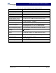
G3L-1929- Installation and Service Manual Table 1-2 G3L-1929-75 Amplifier Electrical Specifications Frequency Range 1930 - 1990 MHz Channel Spacing 12.5 KHz Output Power: +50.8 dBm (120 Watts) Input Power -10.0 dBm max. RF Gain +60 dB ±1.0 dB @ +27Vdc, 25° C RF Gain Flatness over the operating frequency range ±0.1 dB over any 1.25 MHz (over the frequency range). Gain Flatness: ±0.5 dB (1930 MHz – 1990 MHz) Normal Operating Voltage +27 Vdc ±1V Nominal (±5%) 1Vpp ripple (100-120 Hz) max.
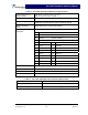
G3L-1929-75 Installation and Service Manual Table 1-3 G3L-1929-120 Amplifier Mechanical Specifications Physical Dimension of MCPA (inches) Front panel: 13.98 W x 3.90 H x 0.118 D Body: 11.61 W x 3.75 H x 17.56 D Weight Approximately 28.6 pounds (13 killograms) Connector Type D-sub, Hybrid, Plug-in Type RF connector: PKZ 26-0020 series straight plug type (Phoenix Co.) refers to attached drawing.
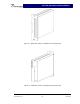
G3L-1929- Installation and Service Manual Figure 1-1 Model G3L-1929-120 Amplifier Front Isometric View Figure 1-2 Model G3L-1929-120 Amplifier Rear Isometric View Copyright Powerwave Technologies, Inc., May 2003. All rights reserved 044-05138 Rev.
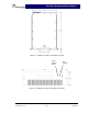
G3L-1929- Installation and Service Manual Figure 1-3 Model G3L-1929-120 Amplifier Top View Power ON/OFF Switch LED Indicator Figure 1-4 Model G3L-1929-120 Amplifier Front Panel Copyright Powerwave Technologies, Inc., May 2003. All rights reserved 044-05138 Rev.
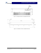
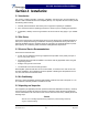
G3L-1929- Installation and Service Manual 21WA4 Connector l Figure 1-5 Model G3L-1929-120 Amplifier Rear Panel Figure 1-6 Model G3L-1929-120 Amplifier Side View Copyright Powerwave Technologies, Inc., May 2003. All rights reserved 044-05138 Rev.
G3L-1929- Installation and Service Manual Section 2. Installation 2-1 Introduction This section contains unpacking, inspection, installation instructions and recommendations for the G3L-1929-120 Multi-Carrier Power Amplifier (MCPA). It is important that the licensee perform the following tasks correctly. 1. Carefully read all material in this section prior to equipment unpacking or installation. 2. Also, read and review the operating procedures in section 3 prior to installing the equipment. 3.
G3L-1929- Installation and Service Manual 1. Visually inspect the MCPA for damage that may have occurred during shipment. 2. Check for evidence of water damage, bent or warped chassis, loose screws or nuts, or extraneous packing material in the connector(s). CAUTION Before applying power, make sure that all connectors are secure. Make sure that the input and output are properly terminated at 50 ohms. Do not operate the system without a load attached.
G3L-1929- Installation and Service Manual 4. Measure primary DC input voltage. DC input voltage should be +27 Vdc ±1.0 Vdc. If the DC input voltage is above or below the limits, call and consult Powerwave before you turn on your amplifier system. 5. Refer to section 3 for initial turn-on and checkout procedures.
G3L-1929- Installation and Service Manual Section 3. Operating Instructions 3-1 Introduction This section contains a description of the G3L-1929-120 Multi-Carrier Power Amplifier (MCPA) controls and indicators and initial start-up and operating procedures. 3-2 Controls and Indicators The controls and indicators for the G3L-1929-120 Power Amplifier consist of the primary power On/Off/Reset switch and status indicator LED as shown in figure 3-1.
G3L-1929- Installation and Service Manual 3-3 Initial Start-Up and Operating Procedures To perform the initial start-up, proceed as follows: 1. Verify that all input and output cables are properly connected. CAUTION Before applying power, make sure that the input and output of the amplifier are properly terminated at 50 ohms. Do not operate the amplifier without a load attached. Refer to table 1-1 for input power requirements. Excessive input power may damage the MCPA.
G3L-1929- Installation and Service Manual Section 4. Principles of Operation 4-1 Introduction This section contains a functional description of the G3L-1929-120 Multi-Carrier Power Amplifier (MCPA). 4-2 RF Input Signal The maximum input power for all carrier frequencies to the amplifier should not exceed the limits specified in the appendix A specifications. 4-3 RF Output Load The load impedance should be as good as possible (VSWR of 1.
G3L-1929- Installation and Service Manual Figure 4-1 Multi-Carrier Power Amplifier Functional Block Diagram 4-4.1 Preamplifier The carrier is applied to the input port of the amplifier. This signal is fed to the preamplifier stage where it is amplified using two stages of class A mode amplifiers. The output of the preamplifier is then split into two paths, one to the main amplifier and one to the error amplifier. 4-4.2 Main and Error Amplifiers The main amplifier provides approximately 14.
G3L-1929- Installation and Service Manual 4-4.3 Alarm Monitoring and Control The alarm logic controls the +5 Vdc bias voltage that shuts down the amplifier. During routine operation, all normal variations are automatically compensated for by the feed-forward loop control. However, when large variations occur beyond the adjustment range of the loop control, a loop fault occurs. When this happens, an alarm indicator is illuminated on the front panel of the subrack.
G3L-1929- Installation and Service Manual Section 5. Maintenance 5-1 Introduction This section contains periodic maintenance and performance test procedures for the G3L-1929120 Multi-Carrier Power Amplifier (MCPA). NOTE Check your sales order and equipment warranty before attempting to service or repair the unit. Do not break the seals on equipment under warranty or the warranty will be null and void.
G3L-1929- Installation and Service Manual 5-4 Performance Test Performance testing should be conducted every 12 months to ensure that the amplifier system meets the operational specifications listed in Table 5-3. Also verify system performance after any amplifier module is replaced in the field. The test equipment required to perform the testing is listed in table 5-2, and the test setup is shown in figure 5-1.
G3L-1929- Installation and Service Manual Figure 5-1 Amplifier Test Setup Diagram Table 5-3 G3L-1929-120 Amplifier Test Data Sheet DATE _________________________________ MODULE S/N _________________________ Test Conditions: Load and Source Impedance: 50 Ohms VSWR: < 1.5:1 Supply Voltage: +27 Vdc ±0.1 Vdc Test RF Gain Spurious Emissions Gain Flatness Input Return Loss PASS Specification Vcc = 27 Vdc PO = See table 1-4 Freq.
G3L-1929- Installation and Service Manual 5-5 Field Replacement of the Module The GL3-1929-120 multi-carrier power amplifier module can be replaced in the field on site by a qualified technician with experience maintaining RF power amplifiers and similar equipment: To replace a power amplifier module, proceed as follows: 1. Set On/Off switch on the front panel of the amplifier module to Off (down). 2. Loosen the two thumbscrews that secure amplifier module to the subrack.
G3L-1929- Installation and Service Manual Section 6. Troubleshooting 6-1 Introduction This section contains a list of problems that could occur and a few suggested actions that can correct the problem. If the suggested corrective action does not eliminate the problem, please contact your Powerwave field representative or the factory for further instructions (refer to paragraph 6-3). NOTE Check your sales order and equipment warranty before attempting to service or repair the unit.