
User's Manual
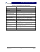
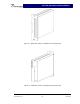
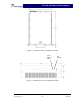
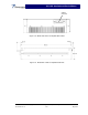
Table Of Contents

G3L-1929- Installation and Service Manual
Section 1. General Description
1-1 Introduction
This manual contains information and procedures for the installation and operation of Powerwave
Technologies, Inc.’s G3L-1929-120 Multi-Carrier Power Amplifier (MCPA). This manual is organ-
ized into the following sections:
Section 1 General Description
Section 2 Installation
Section 3 Operating Instructions
Section 4 Principles of Operation
Section 5 Maintenance
Section 6 Troubleshooting
1-2 General Description
The G3L-1929-120 Power Amplifier shown in figures 1-1 through 1-6, operates in the 60 MHz fre-
quency band from 1930 MHz to 1990 MHz with channel spacing of 12.5 kHz. The amplifier provides
a typical gain of 60 dB to produce a typical output of 60 Watts (47.8 dBm). The G3L-1929-120 am-
plifier generates approximately 2300 BTUs of heat at full power. The amplifiers are modular in
design, and ideally suited for use in GSM base stations.
1-3 Ordering Information
Table 1-1 lists major system component numbers and descriptions for use in ordering booster
amplifiers or components.
Table 1-1 Major System Components
Component
Number
Description
G3L-1929-120 120-Watt Amplifier, +27 VDC
1-4 Functional and Physical Specifications
Electrical, mechanical, and environmental specifications for the G3L-1929-75 amplifier are listed
in tables 1-2, 1-3, and 1-4 respectively.
1-5 Equipment Changes
Powerwave Technologies, Inc. reserves the right to make minor changes to the equipment, in-
cluding but not limited to component substitution and circuitry changes. Changes that impact this
manual may be incorporated in a later revision of the manual.
Copyright Powerwave Technologies, Inc., May 2003. All rights reserved
044-05138 Rev. A 1-1 May 2003