
User's Manual


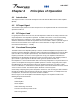
Table Of Contents

044-05117
Chapter 4 Principles of Operation
4-1 Introduction
This chapter contains a functional description of the G3L-850-135 Multi-Carrier Power Amplifier
(MCPA).
4-2 RF Input Signal
The maximum input power for all carrier frequencies to the amplifier should not exceed the limits
specified in Table 1-2
4-3 RF Output Load
For good power transfer to the RF load, the load impedance should be as closely matched to the
output impedance of the amplifier as possible. A VSWR of less than 1.5:1 across the working
band of frequencies is satisfactory. If the amplifier is operated into a filter, it maintains its
distortion characteristics outside the signal band even if the VSWR is infinite. A parasitic signal of
less than one-watt incident on the output will not cause distortion at a higher level than the
normal forward distortion (i.e. -65 dBc).
4-4 Functional Description
The Multi-Carrier Power Amplifier (MCPA) is a linear, feedforward amplifier that operates in the
frequency band from 869 MHz to 894 MHz with an instantaneous bandwidth of less than 25 MHz
(refer to Table 1-2 for amplifier specifications). The instantaneous bandwidth is the maximum
frequency band that a set of two or more signals can occupy .The amplifier’s instantaneous
bandwidth is set automatically and does not require any manual setup. The amplifier provides a
gain of 63 dB. Typical outputs for different carrier types are specified in Table 1-2.
Each amplifier is a self-contained module and is functionally independent of any other MCPA in a
system. The amplifiers are designed for parallel operation to achieve a high peak power output.
Each MCPA has an alarm board that monitors the amplifier performance. If a failure or fault
occurs in an MCPA, it is transmitted to a subrack system via the D-sub 21WA4 connector located
at the rear of the module. The subrack reports all alarms to the host system.
Continuously comparing active paths with passive references, and correcting for small variations
through RF feedback controls maintain constant gain. All gain variations, for example those due
to temperature, are reduced to the passive reference variations.
Refer to Figure 4-1 for the amplifier functional block diagram. The amplifier consists of the
following major functional blocks:
• Preamplifier
• Main amplifier
• Error amplifier
• Alarm monitoring and control
• First and second loop control circuits
• Pilot tone generator
Installation and Service Manual - G3L-850-135 Multi-Carrier Power Amplifier 4-1