
User's Manual
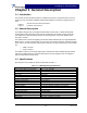
Table Of Contents

Installation & Service Manual
© Copyright Powerwave Technologies, Inc., January 2005. All rights reserved
Chapter 2 Installation and Operation
2-1 Introduction
This section contains operating instructions for the Power Amplifier Radio Module (PARM).
2-2 Installation
The PARM module is designed to be directly installed into the radio module.
2-2.1 Alarms Interface Connector
Pin Number Signal Comment
1 PA_VER_RADO From PARM TO LRM
2 PA_VER_RAD1 From PARM TO LRM
3 PA_VER_RAD2 From PARM TO LRM
4 PA_VER_RAD3 From PARM TO LRM
5 PA_VER_RAD4 From PARM TO LRM
6 GND
7 GND
8 PA_ID_LDMOS0 From PARM TO LRM
9 PA_VG_LDMOS0 From LRM TO PARM
10 GND
11 GND
12 PA_ID_DRIVER From PARM TO LRM
13 PA_ALA_TPTR_OUT From PARM TO LRM
14 GND
15 GND
16 PA_OFF From LRM TO PARM
17 PA_VG_LDMOS1 From LRM TO PARM
18 GND
19 PA_ID_LDMOS1 From PARM TO LRM
20 PA_P_OUT From PARM TO LRM
2-2.2 Alarm Descriptions
• High Temperature – A temperature monitor located inside the PARM indicates the
alarm status if the temperature exceeds the defined threshold.
• High Current - This alarm indicates when a high current is pending that could dam-
age the PARM if the system continues to operate.
2-1 January 2005