Wideband Radio Head Installation and Service Manual 044-05251 Rev A February 2007
© 2007 Powerwave Technologies Incorporated. All rights reserved. Powerwave Technologies and the Powerwave logo are registered trademarks. Powerwave Technologies Inc. reserves the right to make changes to the documentation and equipment, including but not limited to component substitution and circuitry changes. Changes that impact this document may subsequently be incorporated in a later revision of this document.
Wideband Radio Head Revision Record Revision Record Revision Letter Date of Change Reason for Change 3A August 2005 Original VD203 66 A December 2006 Document number changed to 044-05251 and manual updated 044-05251 Rev A i
This Page Intentionally Left Blank ii 044-05251 Rev A
Table of Contents Abbreviations . . . . . . . . . . . . . . . . . . . . . . . . . . . . . . . . . . . . . . . . . . . . . . . . . . . . . . . . . . . . . . . . . . . . . . . v Chapter 1 - Product Description Introduction . . . . . . . . . . . . . . . . . . . . . . . . . . . . . . . . . . . . . . . . . . . . . . . . . . . . . . . . . . . . . . . . . . . . . . . .1-1 Scope of Manual . . . . . . . . . . . . . . . . . . . . . . . . . . . . . . . . . . . . . . . . . . . . . . . . . . . . . . . . . . . . . . . .
Wideband Radio Head Wideband Radio Head PSU . . . . . . . . . . . . . . . . . . . . . . . . . . . . . . . . . . . . . . . . . . . . . . . . . . . . . . . . . . . . . . . . . . . . . . . . . .2-9 Software and Hardware Compatibility . . . . . . . . . . . . . . . . . . . . . . . . . . . . . . . . . . . . . . . . . . . . . . . . . . .2-10 Chapter 3 - Installation Introduction . . . . . . . . . . . . . . . . . . . . . . . . . . . . . . . . . . . . . . . . . . . . . . . . . . . . . . . . . . . . . . . . . . .
Wideband Radio Head List of Figures List of Figures 1-1 1-2 1-3 1-4 1-5 1-6 1-7 1-8 Safety Distance to Active Antenna . . . . . . . . . . . . . . . . . . . . . . . . . . . . . . . . . . . . . . . . . . . . . . . . . .1-4 Powerwave Wideband Radio Head (WRH) . . . . . . . . . . . . . . . . . . . . . . . . . . . . . . . . . . . . . . . . . . . .1-5 Standard WRH Sub Unit Locations . . . . . . . . . . . . . . . . . . . . . . . . . . . . . . . . . . . . . . . . . . . . . . . . . .
Wideband Radio Head Wideband Radio Head 3-4 Initial Startup Procedure . . . . . . . . . . . . . . . . . . . . . . . . . . . . . . . . . . . . . . . . . . . . . . . . . . . . . . . . .3-10 4-1 4-2 4-3 4-4 4-5 Recommended Periodic Maintenance . . . . . . . . . . . . . . . . . . . . . . . . . . . . . . . . . . . . . . . . . . . . . . .4-1 Alarm Troubleshooting . . . . . . . . . . . . . . . . . . . . . . . . . . . . . . . . . . . . . . . . . . . . . . . . . . . . . . . . . . .4-1 FON Replacement Procedure .
Wideband Radio Head Abbreviations Abbreviations The following list of abbreviations are used throughout this manual, the software, and the repeater: AGC Automatic Gain Control ALI Alarm Interface AMPS Advanced Mobile Phone Service BA Booster Amplifier BeO Beryllium Oxide BMU Base Station Master Unit BS Base Station, BS antenna = towards the base station BSA Band Selective Amplifier BSel Band Selective BTS Base Transceiver Station CDMA Code Division Multiple Access CHE Channel Amplif
Wideband Radio Head NiCd Nickel Cadmium NMT Nordic Mobile Telephone system NOC Network Operations Center OCM Optical Converter Module OMS Operation and Maintenance System PCN Personal Communication Network (same as DCS) PCS Personal Communication System POI Point of Interconnect PSM Power Supply Module PTFE Polytetrafluoro Ethylene (Teflon) R2R Repeater-to-Repeater RCI Remote Control Interface RCU Remote Control Unit RCM RF Converter Module RF Radio Frequency RIA Repeater-to-R
Chapter 1 Product Description Introduction This manual contains information and procedures for installation, operation, and maintenance of the Wideband Radio Head (WRH). The manual is organized into chapters as follows. Chapter 1 - Product Description Chapter 2 - Controls and Indicators Chapter 3 - Installation Chapter 4 - Maintenance Chapter 5 - Specifications Scope of Manual This manual is intended for use by service technicians familiar with similar types of equipment.
Wideband Radio Head Safety coaxial cable insulation. No particular measures are to be taken in case of fire because the emitted concentration of hydrogen fluoride is very low. • A lithium battery is permanently mounted on CU units, and in FON and OCM units. Due to the risk of explosion, this battery must only be removed from the board by an Powerwave authorized service technician. • NiCd batteries are mounted on the FON unit. These batteries contain environmental poisonous substances.
Safety Wideband Radio Head FrequencyRadiation power 900MHz 4.5W/m² 1800MHz 9.0W/m² 2100MHz 10.0W/m² For antennas larger than 20cm the maximum radiation power can be calculated by using the following formula: P S = --------------------2 4×π×r whereS = Radiation power in W/m² P = Output power in W r = Distance between antenna and human in meter To tackle the worst case successfully, the calculation does not consider system power reducing actions, such as power control and DTX.
Wideband Radio Head Safety 100 50 9W/m2 (1800MHz) 10W/m2 (2100MHz) 31.6 4.5W/m2 (900MHz) 40 10.0 35 3.2 30 1.0 25 0.3 20 0.1 15 0.03 Antenna output power in W Antenna output power in dBm 45 0.01 10 0 0.1 0.2 0.3 0.4 0.5 0.6 0.7 0.8 0.9 1.0 1.1 1.2 1.3 1.4 Safety distance to antenna in meter Figure 1-1 Safety distance to active antenna. Indoor UMTS WRH output power Feeder loss Antenna gain EIRP +24dBm –5dB +3dBi +22dBm The safety distance can be read to 0.
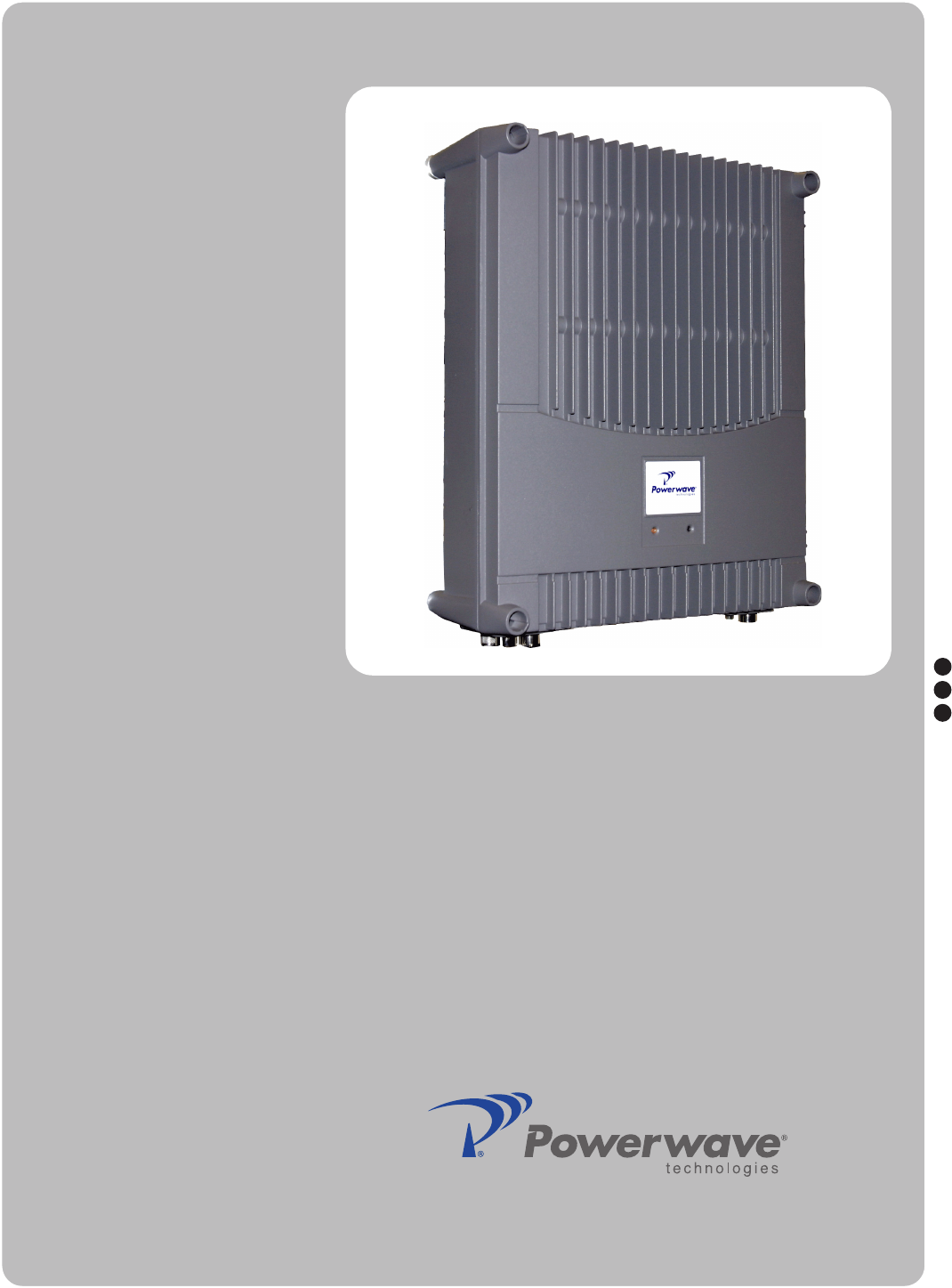
Overview Wideband Radio Head Overview Figure 1-2 Powerwave Wideband Radio Head (WRH) Powerwave WRHs work as bi-directional on-frequency amplifiers used to fill out uncovered areas in wireless mobile systems such as base station fringe areas, tunnels, convention centers, airports and business buildings. It receives, amplifies and transmits signals to/from a base transceiver station (BTS) to/from mobile stations (MS) with both directions being served simultaneously.
Wideband Radio Head Overview WRH-V The WRH-V is designed to provide a higher output power level and comes equipped with a MCPA in the downlink path. The MCPA reduces the number of bands to one band per MCPA used in the cabinet and an additional one band if a high cover is used. The MCPA is located in the cabinet and is supplied from the existing PSU. For two bands, a high cover is used.
Overview Wideband Radio Head P36 P11 P34 V2 P12 P13 P29 P14 P22 V1 XOB 1 2 1 16 1 V2 P28 1 P36 2 16 LED P22 4 P34 16 1 15 1 6 1 16 P5 P3 1 c b a 8 15 P26 16 9 b a 16 P4 1 c b a 9 1 P2 32 c b a P31 PC 5 P32 M ODEM W6B 10 1 1 LNA DOWN-LINK 6 V6 V6 1 6 5 1 GND 7 P21 PSU ALLGON INNOVATION SWEDEN M 105 R6 GND P35 PARKING FOR W5 8 P32 P24 10 P33 ALARM AUX1 W5 P24 2 1 1 5 P27 16 P25 1 6 9 8 15 1 P29 P23 LNA UP-LINK V6B P25 15 6 2
Wideband Radio Head Overview Signals from the DPX output are fed to the LNA input connector IN. OUT1 and OUT2 outputs feed the WBAs of the same signal direction. The signal level in these connectors are +20dB referenced to the antenna input. Another output, OUT LOW, is an expansion output for an additional LNA if the WRH is equipped in the cover part of the chassis. The gain to this connector is +2dB.
Overview Wideband Radio Head Alarm Interface PCBA (ALI) and Remote Control Interface PCBA (RCI) The ALI handles alarms and alarm communication. It is replace with an RCI if an RCU is used and provides an interface between the CU and an RCU for remote communication via modem. The RCI also handles alarms and alarm communication. Either unit is located in the lower left part of the shielded DIA frame.
Wideband Radio Head Overview LNA - UL LNA - DL 1 2 3 WBA DL/UL PA DL BA DL 4 5 6 7 WBA DL/UL PA DL BA DL FON DPX FON DPX FOU ALI/RCI 8 FOU ALI/RCI CU CU PSU PSU (RCU) (RCU) Figure 1-8 Standard WRH with Booster Option Sub Unit Locations WRH-V The WRH-V has a configuration similar to the standard WRH with the exception of a the MCPA that boosts the ouput DL signal from the PA. The MCPA is located at positions 3 and 4 in the cabinet.
Overview Wideband Radio Head Fiber Optic Distribution Networks Fiber optic networks are setup identically to data networks. WRHs are connected is a star configuration as illustrated in Figure 1-6. In this example, a Base Station Master Unit (BMU) is fed by a BTS via an RF cable. An Optical Converter Module (OCM) could also be used depending on the system configuration. The BMU or OCM contain three FONs and provide continuity to the FONs in the four WRHs.
Wideband Radio Head Overview This Page Intentionally Left Blank 1-12 044-05251 Rev A
Chapter 2 Controls, Indicators and Connectors Introduction This chapter contains descriptions of the WRH controls, indicators and connectors. Front Cover Indicators Amber Red Figure 2-1 External Indicators Two LEDs are located on the front cover to provide easy identification of a fault in the system. The amber operation LED lights up approximately 15 seconds after the main power is switched on. When the LED is steady, the WRH is ready for operation.
Wideband Radio Head PCBA Indicators PCBA Indicators This following paragraphs describe the LED indicators on the main PCBAs inside the WRH. CU PCBA Figure 2-3 illustrates the ocation of the LEDs on the CU and Table 2-1 describes their indications. WLI DATA POWER BOOT FAULT OPER Figure 2-3 CU PCBA Indicators Table 2-1 CU PCBA LED Indicators LED Description WLI Wire Line Interface. A flashing green LED indicates the unit is receiving data over the subcarrier.
PCBA Indicators Wideband Radio Head FON PCBA The FON is illustrated in Figure 2-4 and the LED indicators are described in Table 2-2. FLI P102 P115 P109 RX P103 P105 P111 P116 P108 P106 P104 P113 P114 Beryllium oxide hazard P110 P101 TX P130 FAULT OPER BOOT POWER DATA WLI/R2R P112 CHARGE BATT Figure 2-4 FON LED Indicators Table 2-2 FON LED Indications LED FLI or F2F Green LED. Fiber Line Interface (FLI). Flashing LED indicates the unit is receiving data over the sub carrier.
Wideband Radio Head PCBA Connectors PCBA Connectors This following Tables list the connections on the main PCBAs inside the WRH. Table 2-3 describes the connections for the WRH-V configured for PCS with diversity and non-diversity and Table 2-4 for Cellular with diversity and non-diversity.
PCBA Connectors Wideband Radio Head DX UL2 C (D) M FON P101 RG223 Not Used Used BA PCBA Table 2-5 lists the connections for the BA PCBA. Table 2-5 BA PCBA Connections Port Connected to P3 P5 on the PA/DL PCBA P4 HI on the service DPX DIA PCBA Figure 2-5 illustrates and Table 2-6 lists the connections on the DIA PCBA.
Wideband Radio Head PCBA Connectors P34 WLI for IP or R2R network P35 PSU, connector 2 P36 WLI for IP or R2R network DPX DPXs are located on the metal cover sheet in the upper part of the cabinet. Service and donor filters are identical. Table 2-7 DPX Connections Service DPX Port ANT Connected to Service antenna (or DPX on the service (MS) DC HI P5 on the PA/DL LO IN on the LNA/UL. P2101 on the WBA PCBA Donor DPX Port Connected to ANT ANT on the FOU/DPX filter.
PCBA Connectors Wideband Radio Head OUT1 P101 on the CHE2/DL, CSA/DL, or BSA/DL PCBA. P2102 on the WBA PCBA. OUT2 P101 on the CHE1/DL channel PCBA. Not used outputs do not need to be terminated. WARNING: Some LNA power transistors may contain beryllium oxide (BeO) that is poisonous. Refer to the Safety section in Chapter 1 FOU – Fiber Optic Unit The FOU is a metal plate on which a FON PCBA, a DPX and fiber optic connectors are assembled.
Wideband Radio Head PCBA Connectors FLI P102 RX P103 P115 P109 P105 P111 P116 P108 P106 P104 P113 P114 Beryllium oxide hazard P110 P101 TX P130 FAULT OPER BOOT POWER DATA WLI/R2R P112 CHARGE BATT Figure 2-8 FON Connector Locations Table 2-10 FON Connectors Port Description P101 SMA, electrical RF input port (to the optical TX port) P107 SMA, electrical RF input port (15dB below the P101 port) P102 SMA, electrical RF output port (from the optical RX port) P103 SMA, electrical RF
PCBA Connectors Wideband Radio Head P130 34-pin, 2-line male, RCU port used for connecting an RCU. The connector contains both the modem connection and RCU power supply. PSU The PSU is located in the bottom middle of the cabinet or in an equipped high cover. The PSU has all the voltages required for the WRH. It has capacity for the radio circuitry, fiber optics, modem, etc., and also supplies the BA if used. Multi-band WRH-Vs always require a second PSU.
Wideband Radio Head P33 Software and Hardware Compatibility Alarm Port (15-pin D-sub female) - Used for external alarm sensors and alarm equipment. It is located on the DIA to the left in the cabinet. The port has four alarm inputs, EAL1 – EAL4, and two alarm outputs. The four alarm inputs are low-level inputs with common ground (AIC). Use insulated switch or relay to initiate alarms (open switches in normal operating mode, closed switches cause alarm).
Software and Hardware Compatibility Wideband Radio Head This information is accurate as of 01/31/2007. As new versions of hardware and software are released without prior notice. Contact your Powerwave sales representative if in doubt about the latest revision status. For detailed information, refer to the release notes for the CU software to be downloaded (normally found in the readme.txt file provided with the program files).
Wideband Radio Head 2-12 Software and Hardware Compatibility 044-05251 Rev A
Chapter 3 Installation Introduction This chapter contains unpacking, inspection and installation instructions for installing and powering up the WRH. Site Survey Powerwave recommends that a site survey be performed prior to equipment ordering or installation. Performing a detailed site survey reduces or eliminates installation and turn-up delays. Pay particular attention to power plant capacity, cooling needs, floor space, and RF/ DC cabling/breaker requirements.
Mounting Wideband Radio Head A 411 Ø14 90 135 144 205 250 300 Figure 3-1 Mounting bracket Normally, the WRH is mounted on a wall, pole, or mast. Figure 3-2 illustrates the installation of the mounting bracket on a wall using four fixing screws and a locking screw.
Wideband Radio Head Mounting Figure 3-3 illustrates the installation of the mounting bracket on a pole using two 5.7” (144mm) U-shaped clamps and a locking screw. Figure 3-3 Attaching the bracket to a pole Figure 3-4 illustrates a mast installation using two 11.8” (300mm) bar-shaped clamps and no locking screw.
Connections Wideband Radio Head After installing the mounting bracket, hang the WRH on the upper supports, as illustrated in Figure 3-5. Tighten the upper and lower mounting screws to secure it into place. Locking cylinders, used to prevent unauthorized removal of the repeater, can be inserted and locked with a key after the lower screws have been tightened.
Wideband Radio Head Connections Fiber Optic and RF Connections Fiber optic and RF cable connections should be verfied both internally and externally before powering up the equipment. This section illustrates the general internal connections of the WRH and WRH-V. Verify these connections with the as-built drawings and documents for you specific system cofiguration. Table 3-1 lists the steps for external connections to the WRH.
Optional Connections Wideband Radio Head WRH-V Figure 3-7 illustrates the WRH-V cables and connections. Figure 3-7 WRH-V Cable Connections Optional Connections Alarms Alarm signals from external sensors are received by an ALI or RCI which forwards them to the CU. The RCI is used if the WRH has an RCU, otherwise the ALI is used. The software on the CU can activate acoustic or visual alarms or direct the alarm to the P33 alarm port for forwarding via an RCU to an OM-Online or OMS workstation.
Wideband Radio Head Optional Connections P28 P33 1 2 1 16 1 V2 1 P36 S->M 1 16 P34 P14 LED P22 4 6 9 16 P5 P3 1 c b a 8 15 P26 16 15 9 b a 5 1 P4 16 c b a 1 P2 32 c b a P32 M ODEM W6 B 10 P31 PC W5 1 P21 PSU AL LGON INN OVATION SWEDEN M 105 R6 P24 1 LNA DOWN-LINK 6 V6 DC DPX 10 P33 ALARM AUX1 MS -20 dB 2 1 9 5 8 P25 P29 1 9 P27 16 1 1 6 P23 LNA UP-LINK DPX TEST -30 dB 15 6 2 1 DC 1 P28 DOO R 2 1 1 X0B 8 3 16 1 15 V1 16 P13 16 P6
Optional Connections Wideband Radio Head P36 P34 1 2 1 16 1 V2 1 P36 1 S->M X0A 1 16 P34 LED P22 4 15 1 6 1 16 P5 P3 1 c b a 8 15 P26 16 b a P27 8 W5 1 P25 1 9 1 P4 1 16 P2 32 c b a c b a P32 MODEM W6B 10 P31 PC P24 2 1 LNA DOWN-LINK 6 V6 10 P33 ALARM P21 PSU AUX1 MS -20 dB 15 P29 1 5 5 TEST 16 1 1 6 9 DPX -30 dB 15 9 6 2 1 P23 LNA UP -LINK DC 2 1 9 P28 DOOR V1 P14 X0B 8 3 16 1 16 P13 16 P6 c b a M->S 2 1 16 P12 P11 5 1 ALLGO
Wideband Radio Head Optional Connections Main Power Breakdown Relay To be able to distinguish PSU faults from power failure, a main power breakdown relay can be used. This relay is not included in the WRH. It has to be mounted outside the WRH cabinet. The relay intended for this purpose must fulfil the following specifications: Closing time: Max. 30 milliseconds Insulation coil/contact: Min. 4KV A main power connected relay must also be in compliance with valid local regulations.
Optional Connections Wideband Radio Head 21-60 Volt DC PSU Installation The 115/220 VAC PSU can be replaced with a 21 to 60 VDC DC PSU as described below.
Wideband Radio Head Commissioning Commissioning Before proceeding, carefully read the Safety section and check all connections made during the installation. To fulfill the IP65 weather protective requirements, ensure cable strain relief bushings are properly tightened. Also, ensure gaskets at cable inlets and on the cabinet are properly fitted and not damaged.
Commissioning Wideband Radio Head This Page Intentionally Left Blank 3-12 044-05251 Rev A
Chapter 4 Maintenance Introduction This chapter contains periodic maintenance and performance test procedures for the WRH. Periodic Maintenance Periodic maintenance requirements are listed in Table 4-1, as well as the intervals at which the tasks should be performed. Table 4-1 Recommeded Periodic Maintenance Task Interval Action Inspection of cables and connectors 12 months Inspect power, RF and Fiber cables for signs of damage or wear (frayed insulation, cracks, punctures, etc.
Troubleshooting Wideband Radio Head PSU FON 2 3 4-2 WRH restart Mains breakdown CU External Critical PSU2 in the cover does not work properly. A sum signal from the PSU2 indicates that at least one voltage output has dropped. If no mains breakdown relay is used, then the alarm will also be sent at mains breakdown. Ceasing PSU2 in the cover works properly again. Ceasing is sent if the PSU2 works at start-up, and there is a corresponding critical PSU2 alarm logged in the Events Log.
Wideband Radio Head 9 Inst. unit lost 10 EEPROM error 11 Log memory fault 12 High temp CU CU Error Compared to the last power on, the CU lacks at least one hardware unit. Error EEP read or write fail. Data cannot be written or read from the EEPROM on the CU PCBA. User parameters are stored in the EEPROM. Error Log memory fault. Indicates that the log memory on the CU PCBA is faulty. The WRH will not work. Not available in all CU software versions.
Troubleshooting Wideband Radio Head 22 23 24 External alarm 3 External alarm 4 External External External Config External alarm input EA2 active more than 1 second. Ceasing External alarm input EA2 no longer active. Config External alarm input EA3 active more than 1 second. Ceasing External alarm input EA3 no longer active. Config External alarm input EA4 active more than 1 second. Ceasing External alarm input EA4 no longer active.
Wideband Radio Head 41 42 44 48 50 RF blocking Antenna isolation Low stability margin Battery backup fault Fiberoptical error Channel #, UL/DL WBA #, Channel #, UL/DL Channel #, UL/DL External FOT fiber optics Ceasing The cause of the alarm has ceased. Error Constant carrier, PA off. Uplink carrier has been constantly above 27dBm more than 10 seconds. Ceasing The cause of the alarm has not been detected for 10 seconds. Warning Low antenna isolation.
Troubleshooting Wideband Radio Head 60 61 65 66 No BCCH detected Gain reduction Overpower alarm RSSI Statistics RSSI Statistics Channel #, UL/DL Channel #, UL/DL Warning No signal strength on the channel was above the limit set longer than the time set in the configuration, indicating possible problems with service antenna. The area that the WRH is servicing may be covered by another stronger WRH or BTS.
Wideband Radio Head 92 FON RxLevel alarm FON Warning Received optical level is below any of the two limits (one for Warning and one for Error). Suggested remedy: Check optical cables. Error Received optical level is below any of the two limits (one for Warning and one for Error). Suggested remedy: Check optical cables. Ceasing The cause of the alarm has ceased. 93 FON SPI alarm FON F2F Error The SPI bus connection to the RF modem does not work properly. Suggested remedy: Replace the FON PCBA.
Troubleshooting Wideband Radio Head 110 SW incompatibility MRX Error The MRX and CU software is not compatible. Suggested remedy: Check the software versions and replace the incompatible one. 120 Startup error BSA # Error A hardware error is detected on the BSA PCBA at powering up. 121 Synthesizer fault BSA # Error Unlocked synthesizer. The frequency synthesizer is unlocked and the transmission can take place on an unknown frequency.
Wideband Radio Head Field Replaceable Units Field Replaceable Units The following units can be replaced in the field on-site by a qualified technician with experience maintaining RF equipment: • FON • PSU • WRH FON To replace a FON PCBA, proceed as desribed in the Table 4-3.
Return For Service Procedures Wideband Radio Head WRH To replace a WRH, proceed as desribed in the Table 4-5. Table 4-5 WRH Replacement Procedure Step Action 1 Open WRH door and secure 2 Disconnect main power plug from PSU 3 Verify all cables connected to WRH are labeled before disconnecting, then disconnect all cables 4 Remove mounting screws from bottom legs of WRH and loosen mounting screws in top legs 5 Close and secure door WARNING: A fully loaded WRH can weigh 96lbs.
Wideband Radio Head Repeater-to-Repeater Link (R2R) 1 2 1 16 1 V2 S->M LED P22 4 P34 16 1 15 6 9 1 P28 DOOR 16 P5 P3 1 c b a 8 15 P26 16 5 9 1 16 1 P2 32 c b a P32 MODEM W6B 10 P31 PC 1 P21 PSU ALLGON INNOVATION SWEDEN M105 R6 P24 1 LNA DOWN-LINK 6 V6 DC DPX 10 P33 ALARM AUX1 W5 2 1 P4 c b a 5 MS -20 dB 16 P25 P29 1 9 P27 8 15 1 1 6 P23 LNA UP-LINK DPX TEST -30 dB 15 9 b a 6 2 1 DC 2 1 1 X0B 8 3 V1 P14 c b a 1 X0A 16 P13 16 P6 M->S
Repeater-to-Repeater Link (R2R) Wideband Radio Head PSTN PSTN Figure 4-2 R2R network 4-12 044-05251 Rev A
Chapter 5 Specifications Introduction This chapter provides specifications for the different WRH product line. Table 5-1 WRH Specifications Generic Dimensions (W x H x D in inches) 17.5 x 21 x 7 (low cover) 17.5 x 21 x 11 (high cover) Weight Empty low cover Cabinet with a low cover Cabinet with a high cover Equipped cabinet or high cover w/extra heat sink element 13 lbs (6.0 kg) 50 lbs (22.5 kg) 96lbs (44.0 kg) 41 lbs (18.
Introduction Wideband Radio Head Standard WRH (SMR / iDEN 800 / 900 MHz) Frequency band UL 806-824 MHz; 896-901 MHz Frequency band DL 851-869 MHz; 935-940 MHz Max absolute delay <300 ns Filter bandwidth (remotely adjustable) 0.5-16.
Wideband Radio Head Introduction Instantaneous bandwidth 60 MHz Maximum input power (non-destructive) +13dBm Return Loss 14dB TX band IMD < -60dBc (1930-1990 MHz) Full power 8 EDGE carriers TX spurious in RX band < -111dBm / 200kHz Full power 8 EDGE carriers Output power +43dBm Noise figure excluding fiber optic link 4dB 044-05251 Rev A 5-3
Introduction Wideband Radio Head This Page Intentionally Left Blank 5-4 044-05251 Rev A
Appendix A Block Diagrams Introduction This appendix describes the main signals paths for the WRH. Standard WRH PA - DL BA P4 P3 P5 P4 WBA FOU LNA DL P1101 FLI P1401 FON DPX RX P102 TX P101 HI UL P2401 BMU OCM LNA - UL LNA P2101 OUT1 ANT LO IN RCU WLI P34/ P36 CU P130 PSU P130 ALI / RCI RCI P31 P33 Figure A-1 Standard WRH Block Diagram Figure A-1 illustrates a single band WRH block diagram.
WRH-V Wideband Radio Head WRH-V MCPA PA - DL P4 P3 P5 P4 WBA FOU LNA DL P1101 FLI P1401 FON DPX RX P102 TX P101 HI UL P2401 BMU OCM LNA - UL LNA P2101 OUT1 LO ANT IN RCU WLI P34/ P36 CU P130 PSU P130 ALI / RCI RCI P31 P33 Figure A-2 WRH-V Block Diagram Figure A-2 illustrates a block diagram the WRH-V. The WRH-V is always fed by a BTS via either a BMU or an OCM.
Powerwave Installation and Service Manual Corporate Headquarters Powerwave Technologies, Inc. 1801 East St. Andrew Place Santa Ana, CA 92705 USA Tel: 714-466-1000 Fax: 714-466-5800 www.powerwave.com Main European Office Antennvägen 6 SE-187 80 Täby Sweden Tel: +46 8 540 822 00 Fax: +46 8 540 823 40 Main Asia-Pacific Office 23 F Tai Yau Building 181 Johnston Road Wanchai, Hong Kong Tel: +852 2512 6123 Fax: +852 2575 4860 ©Copyright March 2005, Powerwave Technologies, Inc. All Rights reserved.