COVERAGE SYSTEMS N E X U S R T R E P E AT E R I N S T A L L AT I O N A N D S E R V I C E M A N U A L 044-05311 R E V.
© 2008 Powerwave Technologies Incorporated. All rights reserved. Powerwave Technologies and the Powerwave logo are registered trademarks. Powerwave Technologies Inc. reserves the right to make changes to documentation and equipment, including but not limited to component substitution and circuitry changes. Changes that impact this document may be subsequently incorporated in a later revision of this document.
Nexus RT Effective Pages Revision Record Revision Letter A 044-05311 Rev A Date of Change October 2008 Reason for Change New (original) i
Effective Pages Nexus RT This page intentionally left blank ii 044-05311 Rev A
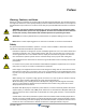
Preface Warning, Cautions, and Notes Warnings, Cautions, and Notes are found throughout this manual where applicable. The associated icons in warnings and cautions are used to quickly identify a potential condition that could result in the consequences described below if precautions are not taken. Notes clarify and provide additional information to assist the user. WARNING: The warning symbol means danger. You are in a situation that could cause bodily injury or death.
Electrostatic Discharge (ESD) Nexus RT Warning Signs The following warning signs must be observed and be kept clean and readable. Beryllium oxide This warning sign to the left is applied to boards and units which contain beryllium oxide parts. Beryllium oxide hazard This warning sign below is applied at the bottom, inside the cabinet, below the power supply unit.
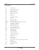
Nexus RT List of Acronyms List of Acronyms AC Alternating Current ADC Analogue-to-Digital Converter ALC Automatic Level Control BTS BaseTransceiver Station DAC Digital to Analog Converter dB Decibel DC Direct Current DDA Donor Duplexer Assembly DL Downlink DPA Donor Power Amplifier DSP Digital Signal Processor EEPROM Electrically Erasable Programmable Read Only Memory EMC ElectroMagnetic Compatibility EMI ElectroMagnetic Interference EMS Element Management System FCC Federa
List of Acronyms vi Nexus RT MCU Microcontroller Unit MFLOPs Million Floating Point Operations per second MHz Mega Hertz Msps Million of Samples Per Second MTBF Mean Time Between Failures MTTR Mean Time to Repair NEP Network Elerment Processor NMS Network Management System OA&M Operations, Administration and Maintenance OTA Over the Air PA Power Amplifier PCS Personal Communications Services PCBA Printed Circuit Board Assembly RCM RF Converter Module RF Radio Frequency RSSI
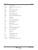
Table of Contents Warning, Cautions, and Notes . . . . . . . . . . . . . . . . . . . . . . . . . . . . . . . . . . . . . . . . . . . . . . . . . . . . . . . . . vii Safety . . . . . . . . . . . . . . . . . . . . . . . . . . . . . . . . . . . . . . . . . . . . . . . . . . . . . . . . . . . . . . . . . . . . . . . . . . . . vii Human Exposure to RF Radiation . . . . . . . . . . . . . . . . . . . . . . . . . . . . . . . . . . . . . . . . . . . . . . . . viii Electrostatic Discharge (ESD) . . . . . . . . . . .
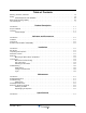
List of Figures 1-1 1-2 1-3 1-4 Nexus RT Block Diagram . . . . . . . . . . . . . . . . . . . . . . . . . . . . . . . . . . . . . . . . . . . . . . . . . . . . . . . . .1-2 Nexus RT Repeater Enclosure . . . . . . . . . . . . . . . . . . . . . . . . . . . . . . . . . . . . . . . . . . . . . . . . . . . .1-2 Nexus RT Dual Slice Configuration . . . . . . . . . . . . . . . . . . . . . . . . . . . . . . . . . . . . . . . . . . . . . . . . .1-3 Nexus RT Connections . . . . . . . . . . . . . . . . . . . . . . . .
Chapter 1 Product Description Introduction This manual contains information and procedures for installation, operation, and maintenance of the Nexus RT epeater, referred to in this manual as the Nexus RT.
Overview Nexus RT Figure 1-1 shows a block diagram of the Nexus RT.
Nexus RT Overview Main Chassis Wireless Modem Network Element Processor Board Power Supply Donor Duplexer Assemblies (DDA) Service Duplexer Assemblies (SDA) Input/Output Board Figure 1-3 Nexus RT Dual Slice Configuration Nexus RT Connections Figure 1-4 Nexus RT Connections 044-05311 Rev A 1-3
Overview Nexus RT This page intentionally left blank 1-4 044-05311 Rev A
Chapter 2 Indicators and Connectors Introduction This chapter contains descriptions of the controls, indicators, and connectors for the Nexus RT. Indicators Four LEDs, shown in Figure 2-1 and described in Table 2-1, are located on the bottom of the Nexus RT to provide easy identification of system status.
Connectors Nexus RT Connectors Figure 2-2 and Table 2-2 describe the connectors available on the Nexus RT repeater.
Chapter 3 Installation Introduction This chapter contains unpacking and inspection, and mounting installation instructions for powering up the Nexus RT. Site Survey Powerwave recommends that a site survey be performed prior to ordering or installing equipment. Performing a detailed site survey reduces or eliminates installation and turn-up delays. Pay particular attention to power plant capacity, cooling needs, floor space, and RF/DC cabling/breaker requirements.
Mounting Nexus RT Mounting Use the mounting bracket provided (as shown in Figure 3-1) to mount the Nexus RT on a wall. Figure 3-1 Mounting Bracket Figure 3-2 illustrates the installation of the mounting bracket on a wall using six fixing screws.
Nexus RT Mounting Mounting the Nexus RT on the Bracket 1. After installing the mounting bracket, insert the mounting screws into the bracket, then hook the upper supports on the Nexus RT over the mounting screws, as illustrated in Figure 3-3. Figure 3-3 Attaching the Nexus RT upper supports 2. Align the lower supports with the mounting holes on the bracket, then insert the lower mounting screws, as shown in Figure 3-4 Figure 3-4 Attaching the Nexus RT lower supports 3.
Connections Nexus RT Connections This section describes general examples of how to connect the input and output ports on the Nexus RT. Figure 3-5illustrates the connections for the Nexus RT. . 3 4 1 5 6 2 Figure 3-5 Nexus RT Cable Connections 1— RF Input/Output – Donor Side. The reverse transmit and forward receive signals are duplexed onto one RF port. There is one donor side connector for each band. 2—RF Input/Output – Service Side.
Nexus RT Connections Attaching the Sunshield The Nexus RT is housed in a cast aluminum, waterproof chassis, with a detachable sunshield approved for outdoor use. To attach the sunshield, align the grooves on the inside of the sunshield with the tabs on the Nexus RT housing and slide the sunshield down until it stops, as shown in Figure 3-6.
Commissioning Nexus RT Commissioning Before proceeding, carefully read the Safety section and check all connections made during the installation. To fulfill the IP65 weather protective requirements, ensure cable strain relief bushings are properly tightened. Also, ensure the gaskets at cable inlets and on the cabinet are properly fitted and not damaged. Initial Startup To complete the initial start-up of the Nexus RT, follow the steps listed below. 1. Turn on the main power. All LEDs will light up. 2.
Nexus RT Commissioning 3. Enter user name “PW_Admin” and password “admin22.” The Home page of the Nexus RT interface displays, as shown in Figure 3-9. Figure 3-9 Nexus RT Home Page For configuration settings, refer to the Nexus RT Software and Configuration Manual (044-XXXXX).
Commissioning Nexus RT This page intentionally left blank 3-8 044-05311 Rev A
Chapter 4 Maintenance Introduction This chapter contains periodic maintenance and procedures to return the Nexus RT for service. Periodic Maintenance Refer to Table 4-1 for Periodic maintenance requirementsand the intervals at which to perform the tasks. Table 4-1 Recommended Periodic Maintenance Task Interval Action Inspection of cables and connectors 12 months Inspect power and RF cables for signs of damage or wear (frayed insulation, cracks, punctures, etc.
Field Replaceable Units Nexus RT Field Replaceable Units There are no field replaceable components in the Nexus RT. If any components fail, plese contact Powerwave for assistance. Return For Service Procedures When returning products to Powerwave, the following procedures will ensure optimum response. Obtaining an RMA A Return Material Authorization (RMA) number must be obtained prior to returning equipment to the factory for service.
Chapter 5 Specifications Introduction This chapter provides specifications for the Nexus RT.
Worldwide Corporate Headquarters 1801 East St. Andrew Place Santa Ana, CA 92705 USA +1 714 466 1000 +1 714 466 5800 FAX www.powerwave.com Main European Office Knarrarnasgatan 7 8tr. 164 40 Kista, Sweden +46 8-540-822-00 +46 8-540-824-91 FAX Main Asia-Pacific Office 23 F Tai Yau Building 181 Johnston Road Wanchai, Hong Kong +852 2512 6123 +852 2575 4860 FAX Powerwave Technologies, Inc. All rights reserved.