$OOJRQ 0LFURZDYH 5DGLR ,QVWDOODWLRQ 0DQXDO Future on Demand.
,03257$17 127,&( 7KLV GRFXPHQW LV VXEMHFW WR UHYLVLRQ ZLWKRXW QRWLFH $OOJRQ $% KDYH QR OLDELOLW\ IRU W\SLQJ HUURUV LQ WKLV GRFXPHQW RU GDPDJHV RI DQ\ NLQG WKDW UHVXOW IURP WKH XVH RI WKLV GRFXPHQW 5HDG WKLV PDQXDO FDUHIXOO\ EHIRUH LQVWDOOLQJ WKH $OOJRQ 0LFURZDYH 5DGLR HTXLSPHQW DQG IROORZ DQ\ DQG DOO LQVWUXFWLRQV VHW IRUWK KHUHLQ 1RQ FRPSOLDQFH ZLWK RU QRQ REVHUYDQFH WR WKH LQVWUXFWLRQV VHW IRUWK LQ WKLV PDQXDO PD\ FDXVH SHUVRQDO LQMXU\ RU GDPDJH WR SURSHUW\ DQG PD\ EH LOOHJDO $OOJRQ $% DQG LWV
&RQWHQWV ,QWURGXFWLRQ Applicable Documents . . . . . . . . . . . . . . . . . . . . . . . . . . . 5 Document Information . . . . . . . . . . . . . . . . . . . . . . . . . . . 5 Syntax . . . . . . . . . . . . . . . . . . . . . . . . . . . . . . . . . . . . . . . 6 6LWH 5HTXLUHPHQWV Safety Requirements . . . . . . . . . . . . . . . . . . . . . . . . . . . . 7 Indoor Requirements . . . . . . . . . . . . . .
Initial Radio Terminal Configuration. . . . . . . . . . . . . . . . 58 Remote Management Connection . . . . . . . . . . . . . . . . . 68 $QWHQQD $OLJQPHQW Tools Required for Antenna Alignment . . . . . . . . . . . . . 80 Preparations . . . . . . . . . . . . . . . . . . . . . . . . . . . . . . . . . 80 Alignment Procedure . . . . . . . . . . . . . . . . . . . . . . . . . . . 81 ,QVWDOODWLRQ 9HULILFDWLRQ DQG 7HVW Checking RF Path Status . .
,QWURGXFWLRQ ,QWURGXFWLRQ $SSOLFDEOH 'RFXPHQWV :/'0 ,QVWDOODWLRQ 0DQXDO This manual describes the installation of the Allgon Microwave Radio including start-up and configuration. :/'0 2SHUDWLRQ DQG 0DLQWHQDQFH 0DQXDO This manual describes how to use a web browser interface to manage the Allgon Microwave Radio. It also contains instructions for troubleshooting and maintenance.
,QWURGXFWLRQ The letters x, y and z in the product numbers listed above are variables that depend on the product variant. For further details concerning product numbers, refer to the respective section in this manual and the Product List (WLDM004). All documents, including this manual, also use the ITU standard designations for traffic channels. However, the information is also valid for ANSI standard applications if not otherwise noted. 6\QWD[ The following typing conventions are used throughout this man
6LWH 5HTXLUHPHQWV 6LWH 5HTXLUHPHQWV 6DIHW\ 5HTXLUHPHQWV 7HUPLQRORJ\ This manual contains two kinds of safety warnings which represent different degrees of danger: &$87,21 7KLV ZDUQLQJ LV XVHG IRU GDQJHUV ZKLFK FRXOG FDXVH LQMXULHV WR SHUVRQQHO RU GDPDJH WR WKH HTXLSPHQW LI LJQRUHG '$1*(5 7KLV ZDUQLQJ LV XVHG IRU GDQJHUV ZKLFK FRXOG FDXVH OLIH WKUHDWHQLQJ LQMXULHV WR SHUVRQQHO RU GHVWUR\ WKH HTXLSPHQW LI LJQRUHG 6DIHW\ 3UHFDXWLRQV • Access to the Allgon Microwave Radio shall be restricted to serv
6LWH 5HTXLUHPHQWV • Do not use any components (screws, nuts etc.) other than those delivered together with the Allgon Microwave Radio equipment or recommended by Allgon AB. • Use the necessary safety devices (helmet, safety line etc.) when working on, or around the mast. Be aware of the risk of falling objects. Secure the integrated Antenna/Radio Frequency Unit before lifting it up the mast. %HU\OOLXP 2[LGH Some components in the Radio Frequency Unit contain beryllium oxide (BeO) which is poisonous if
6LWH 5HTXLUHPHQWV *URXQGLQJ It is recommended to ground all equipment before the power cable is connected. &$87,21 $OO LQGRRU DQG RXWGRRU JURXQGLQJ V\VWHPV RQ WKH LQVWDOODWLRQ VLWH PXVW PHHW WKH UHTXLUHPHQWV RI WKH DSSOLFDEOH QDWLRQDO VWDQGDUGV (OHFWULFDO 6DIHW\ The Allgon Microwave Radio equipment meets the electrical safety requirements in EN 60950.
6LWH 5HTXLUHPHQWV ,QGRRU 5HTXLUHPHQWV ,QGRRU 6SDFH 5HTXLUHPHQWV 7DEOH 6SDFH UHTXLUHPHQWV IRU WKH ,QGRRU 8QLW ,QVWDOODWLRQ : + ' ) Single Indoor Unit 19" 1U 270 mm 70 mm 2U Magazine 19" 2U 2902 mm 70 mm 6U Magazine 19" 6U 2902 mm 70 mm 1. Space required for connecting cables and connectors. 2. The units will extend an additional 20 mm in front of the rack, compared to Single Indoor Unit mounting. All interfaces are accessible on the front of the Indoor Unit.
6LWH 5HTXLUHPHQWV ,QGRRU 3RZHU 5HTXLUHPHQWV 3RZHU 6XSSO\ The power supply should be a two wire power distribution between 20 V and 72 V DC, any polarity. &$87,21 7KH VXSSO\ YROWDJH PXVW QRW H[FHHG 9 ,QWHUQDO 3URWHFWLRQ &LUFXLWV The radio terminal is equipped with two 5 A fuses on the power supply input to the Indoor Unit. These fuses are mounted for safety reasons and can only be exchanged by the manufacturer.
6LWH 5HTXLUHPHQWV ,QGRRU (QYLURQPHQWDO 5HTXLUHPHQWV The Indoor Unit meets the requirements of ETS 300 019-3. 7DEOH 5HTXLUHPHQWV IRU LQGRRU WHPSHUDWXUH DQG KXPLGLW\ &KDUDFWHULVWLF 9DOXH 7HPSHUDWXUH Single units and rack mounted units with >1U spacing (above and below). -25°C to +55°C Rack mounted units with <1U spacing. -25°C to +45°C 1 5HODWLYH +XPLGLW\ 95% RH 1. See ETS 300 019 for detailed requirements for humidity vs. temperature.
6LWH 5HTXLUHPHQWV 2XWGRRU 5HTXLUHPHQWV 2XWGRRU 6SDFH 5HTXLUHPHQWV The standard method for mounting the Radio Frequency Unit (RFU) and the Antenna Unit is to mount them together as one integrated unit. 7DEOH 6SDFH UHTXLUHPHQWV IRU WKH LQWHJUDWHG 5DGLR $QWHQQD 8QLW $QWHQQD 8QLW $ % & ' ( 1 ft. HP antenna 300 mm 380 mm 390 mm 125 mm 165 mm 2 ft.
6LWH 5HTXLUHPHQWV 2XWGRRU 3RZHU 5HTXLUHPHQWV Power supply to the outdoor equipment is fed from the BBU via the radio cable. There is no need for a separate power supply. *URXQGLQJ RI 2XWGRRU (TXLSPHQW *URXQGLQJ RI 5DGLR &DEOH It is recommended to ground the radio cable every 50 metres along the mast, at the foot of the mast and before entering a building. *URXQGLQJ RI $QWHQQD 5DGLR )UHTXHQF\ 8QLW Normally, the Antenna/RF Unit is grounded via the mast’s connection to ground.
6LWH 5HTXLUHPHQWV 2XWGRRU (QYLURQPHQWDO 5HTXLUHPHQWV The outdoor equipment meets the requirements of ETS 300 019-4. 7DEOH 5HTXLUHPHQWV IRU RXWGRRU WHPSHUDWXUH DQG KXPLGLW\ &KDUDFWHULVWLF 2SHUDWLQJ WHPSHUDWXUH 5HODWLYH +XPLGLW\ 2 1 9DOXH -45°C to +45°C 100% RH 1. Excluding solar radiation. 2. See ETS 300 019 for detailed requirements for humidity vs. temperature.
,QGRRU ,QVWDOODWLRQ ,QGRRU ,QVWDOODWLRQ 7RROV 5HTXLUHG IRU ,QGRRU ,QVWDOODWLRQ • Pozidrive screwdriver PZ2 and PZ3 • Necessary tools for assembling the cables and connectors.
,QGRRU ,QVWDOODWLRQ ,QGRRU (TXLSPHQW 7DEOH ,QGRRU HTXLSPHQW 3RV 1 a) 3DUW Indoor Unit, consisting of: 3DUW 1XPEHU – Baseband Unit (BBU) 4W\ 1 1 • ITU WAAB001/01 • ANSI WAAB001/02 b) Traffic Interface Unit (TIU) WAADxxxyyy/zz 1 2 Installation Kit for 19" rack, consisting of: WMSA001 1 a) Rack Mount Screw (M6x16, PZ3) – 4 b) Rack Mount Captive Nut – 4 c) TNC Connector – 1 d) DC Power Connector and Hood – 1 e) 26 pin D-SUB Connector and Hood – 1 WLDM001B
,QGRRU ,QVWDOODWLRQ ,QGRRU $FFHVVRULHV 7DEOH ,QGRRU DFFHVVRULHV 3RV 3DUW 3DUW 1XPEHU 4W\ 1 2U Magazine WMMA001/02 1 2 2U Magazine Installation Kit, consisting of: WMSA002/02 1 a) Rack Mount Screw (M6x16, PZ3) – 4 b) Rack Mount Captive Nut – 4 c) Mounting Rail – 4 d) Mounting Rail Screw (M4x8, PZ2) – 8 3 6U Magazine WMMA001/06 1 2 6U Magazine Installation Kit, consisting of: WMSA002/06 1 a) Rack Mount Screw (M6x16, PZ3) – 8 b) Rack Mount Captive Nut – 8 c)
,QGRRU ,QVWDOODWLRQ %DVHEDQG 8QLW ,QWHUIDFHV RQ WKH %DVHEDQG 8QLW 7DEOH %DVHEDQG 8QLW LQWHUIDFHV 3RV ,QWHUIDFH )XQFWLRQ 1 User interface Control panel with keypad and display for configuring the radio terminal without a PC, and status LEDs for monitoring of the radio terminal. For further information about the control panel, refer to the Operation and Maintenance Manual (WLDM002). 2 9 pin D-SUB jack LM/NMS 1 port, used for connecting a PC or for daisy-chaining radio terminals.
,QGRRU ,QVWDOODWLRQ 3RV 9 ,QWHUIDFH 1 Sofix /Metral connectors 2 )XQFWLRQ Used for connection of the TIU. 1. Ericsson designation 2. Berg designation 7UDIILF ,QWHUIDFH 8QLW All traffic interfaces are located on the TIU of the Indoor Unit. The interfaces are compliant with ITU-T G.703. Two different types of interfaces are available: • Unbalanced interface: SMZ connector, 75 Ω. • Balanced interface: 9 pin or 37 pin D-SUB connector, 120 Ω (E1) / 100 Ω (DS1).
,QGRRU ,QVWDOODWLRQ 8QEDODQFHG ,QWHUIDFHV 7UDIILF ,QWHUIDFH 8QLW XQEDODQFHG LQWHUIDFH ( ( 7DEOH 7UDIILF ,QWHUIDFH 8QLW XQEDODQFHG LQWHUIDFH ( ( 3RV &RQQHFWRU )XQFWLRQ 1 9 pin D-SUB Traffic Channel (E1:17) 2 SMZ Traffic Channel (E3:1), outgoing direction (TX)1 3 SMZ Traffic Channel (E3:1), incoming direction (RX)1 4 9 pin D-SUB Overhead Channel (OH:1) 5 9 pin D-SUB Overhead Channel (OH:2) 1.
,QGRRU ,QVWDOODWLRQ %DODQFHG ,QWHUIDFHV 7UDIILF ,QWHUIDFH 8QLW EDODQFHG LQWHUIDFH [( '6 7DEOH 7UDIILF ,QWHUIDFH 8QLW EDODQFHG LQWHUIDFH [( RU ['6 3RV 1 &RQQHFWRU )XQFWLRQ 9 pin D-SUB Traffic Channel (E1:17 or DS1:17) 2 37 pin D-SUB Traffic Channel (E1:1–8, DS1:1–8) 3 37 pin D-SUB Traffic Channel (E1:9–16, DS1:9–16) 4 9 pin D-SUB Overhead Channel (OH:1) 5 9 pin D-SUB Overhead Channel (OH:2) WLDM001B
,QGRRU ,QVWDOODWLRQ (WKHUQHW ,QWHUIDFHV 7UDIILF ,QWHUIDFH 8QLW (WKHUQHW LQWHUIDFH (WKHUQHW [( '6 7DEOH 7UDIILF ,QWHUIDFH 8QLW (WKHUQHW LQWHUIDFH (WKHUQHW [( '6 3RV ,QWHUIDFH )XQFWLRQ 1 RJ-45 Traffic Channel (10/100baseT) 2 LED, multicolor ON, green: Link available. 3 37 pin D-SUB Traffic Channel (E1:9–12 or DS1:9–12) 4 9 pin D-SUB Overhead Channel (OH:1) 5 9 pin D-SUB Overhead Channel (OH:2) ON, orange: Link activity.
,QGRRU ,QVWDOODWLRQ 0RXQWLQJ WKH ,QGRRU 8QLW There are three different ways of mounting the Indoor Unit: • single unit mounted in 19" rack; • single unit mounted in ETSI rack; and • 2–6 units in a common backplane magazine for 19" rack. The following sections describe 6LQJOH 8QLW 0RXQWLQJ LQ 5DFN and &RPPRQ %DFNSODQH 0RXQWLQJ ,Q 0DJD]LQH IRU 5DFN.
,QGRRU ,QVWDOODWLRQ 6LQJOH 8QLW 0RXQWLQJ LQ 5DFN A B C D 2SWLRQDO SRVLWLRQV IRU PRXQWLQJ WKH EUDFNHWV The brackets can be mounted in four different positions (A–D) to make the Indoor Unit fit in your particular rack set-up. Use a Pozidrive screwdriver PZ2 if you want to move the brackets.
,QGRRU ,QVWDOODWLRQ &RPPRQ %DFNSODQH 0RXQWLQJ ,Q 0DJD]LQH IRU 5DFN 3UHSDULQJ WKH ,QGRRU 8QLW IRU PRXQWLQJ LQ PDJD]LQH &RPPRQ EDFNSODQH PRXQWLQJ RI ,QGRRU 8QLWV LQ 8 RU 8 0DJD]LQH 1RWH The magazine must be mounted in the rack before you remove the transport safety panels. The numbering of the Indoor Units in the magazine starts at the bottom of the magazine; unit number 1 is at the bottom and unit 2 (6) is at the top.
,QGRRU ,QVWDOODWLRQ *URXQGLQJ WKH ,QGRRU 8QLW Normally, the Indoor Unit is grounded via the rack’s connection to ground. If the rack is not connected to ground, it is recommended to ground the Indoor Unit via a separate cable. The cable should be connected to the M6 grounding lug located on the front of the BBU. A flat copper braid is recommended for this purpose.
,QGRRU ,QVWDOODWLRQ ,QVWDOOLQJ WKH &DEOHV IRU WKH ,QGRRU 8QLW 1RWH The connector manufacturer’s instructions for mounting of the connectors must always be followed! 'HILQLWLRQ RI 7; DQG 5; 6LJQDOV 7; signals are defined as signals coming RXW RI the TIU. 5; signals are defined as signals going LQWR the TIU. 8QEDODQFHG 7UDIILF ,QWHUIDFH 60= &RQQHFWRUV Mount the SMZ connectors on the cables and connect the cables to the Indoor Unit.
,QGRRU ,QVWDOODWLRQ 7UDIILF &KDQQHO ' 68% &RQQHFWRUV ( £ '6 £ SLQ ' 68% H[WHUQDO FDEOH FRQQHFWRU UHDU YLHZ 7DEOH 7UDIILF FKDQQHO FRQQHFWRU SLQ DOORFDWLRQ &KDQQHO QR 7; 3LQ QR 5; 3LQ QR &RQQHFWRU 1 19 / 37 18 / 36 E1:1–8, DS1:1–8 2 17 /35 16 / 34 E1:1–8, DS1:1–8 3 15 / 33 14 / 32 E1:1–8, DS1:1–8 4 13 / 31 12 / 30 E1:1–8, DS1:1–8 5 11 / 29 10 / 28 E1:1–8, DS1:1–8 6 9 / 27 8 / 26 E1:1–8, DS1:1–8 7 7 / 25 6 / 24 E1:1–8, DS1:1–8 8 5 / 23 4 / 22 E1:1–8, D
,QGRRU ,QVWDOODWLRQ 7UDIILF &KDQQHO ' 68% &RQQHFWRU ( '6 SLQ ' 68% H[WHUQDO FDEOH FRQQHFWRU UHDU YLHZ 7DEOH 7UDIILF FKDQQHO FRQQHFWRU SLQ DOORFDWLRQ &KDQQHO QR 17 7; 3LQ QR 5/9 5; 3LQ QR 4/8 &RQQHFWRU E1:17, DS1:17 7UDIILF ,QWHUIDFH (WKHUQHW &RQQHFWRUV Mount the RJ-45 connectors on the cables and connect the cables to the Indoor Unit.
,QGRRU ,QVWDOODWLRQ 2YHUKHDG &KDQQHO ' 68% &RQQHFWRUV 2+ 2+ The two 64 kbps OH channels are compliant with ITU-T G.703 requirements for co-directional interfaces. Mount the connectors on the cables according to the pin allocation listed in the table below and connect the cables to the Indoor Unit. Refer to the figure SLQ ' 68% H[WHUQDO FDEOH FRQQHFWRU UHDU YLHZ above for the pin numbering.
,QGRRU ,QVWDOODWLRQ SLQ ' 68% H[WHUQDO FDEOH FRQQHFWRU UHDU YLHZ 7DEOH ([WHUQDO , 2 FRQQHFWRU SLQ DOORFDWLRQ 6LJQDO 3LQ QR Relay 1 1–2 Relay 2 3–4 Relay 3 5–6 Relay 4 7–8 TTL Inputs 10–17 Ground 18 TTL Outputs 19–26 '& 3RZHU &RQQHFWRU ([WHUQDO '& SRZHU FDEOH FRQQHFWRU UHDU YLHZ The power cable should be AWG 16/20 or equivalent. The two wires can be connected to the DC power plug with any polarity. Use a crimping tool to mount the connector pins onto the cable.
,QGRRU ,QVWDOODWLRQ ,QGRRU 5DGLR &DEOH It is recommended to mount a surge arrester at the wall entrance as an adapter between the indoor and outdoor radio cable. The surge arrester should be mounted in a copper plate with a low resistance connection (< 0.1 Ω) to ground on the outside. This will protect the indoor equipment in case of lightning strikes. It is also recommended to fasten the length of the indoor radio cable to the rack or in an existing cable bundle.
2XWGRRU ,QVWDOODWLRQ 2XWGRRU ,QVWDOODWLRQ 7RROV 5HTXLUHG IRU 2XWGRRU ,QVWDOODWLRQ • Pozidrive screwdriver PZ2 • 17 mm torque wrench • Necessary tools for assembling the cables and connectors. 2XWGRRU (TXLSPHQW 7DEOH 2XWGRRU HTXLSPHQW 3RV 3DUW 3DUW 1XPEHU 4W\ 1 Radio Frequency Unit (RFU) WAAAxxxyy/zz 1 2 Antenna Unit (including Mast Mounting Bracket) WAACxxxyy/zz 1 WLDM001B
2XWGRRU ,QVWDOODWLRQ &KRRVLQJ 9HUWLFDO RU +RUL]RQWDO 3RODUL]DWLRQ The position of the RFU determines the polarization of the radio signal. The handle serves as an indicator: horizontal handle = horizontal polarization, vertical handle = vertical polarization. The coaxial connector on the back of the Antenna Unit must fit the connector on the RFU. Use a Pozidrive screwdriver PZ2 if you need to move the connector on the Antenna Unit. 1RWH Do not remove the screw or the washer when you move the connector.
2XWGRRU ,QVWDOODWLRQ ,QWHJUDWLQJ $QWHQQD 8QLW DQG 5DGLR )UHTXHQF\ 8QLW 1. Remove the plastic covers for moisture protection from the waveguides on the RFU and the Antenna Unit. &$87,21 $IWHU WKH SODVWLF FRYHUV KDYH EHHQ UHPRYHG PDNH VXUH WKDW QR PRLVWXUH HQWHUV WKH ZDYHJXLGHV ,QWHJUDWLQJ WKH $QWHQQD 8QLW DQG WKH 5DGLR )UHTXHQF\ 8QLW 2. Hook the circular part of the RFU, containing the waveguide, onto the locking device on the back of the Antenna Unit.
2XWGRRU ,QVWDOODWLRQ 4. Use the 17 mm wrench to fasten the RFU by turning the locking screw on the bottom of the antenna 1/4 turn. You will feel a gentle click when the RFU is locked in position. Stop turning when you feel the resistance increasing. &$87,21 'R QRW FRQWLQXH WXUQLQJ WKH ORFNLQJ VFUHZ ZKHQ \RX IHHO WKH UHVLVWDQFH LQFUHDVLQJ &$87,21 :KHQ \RX FDUU\ RU OLIW WKH $QWHQQD 5) 8QLW XVH WKH KDQGOH RQ WKH WRS RI WKH DQWHQQD 7KH KDQGOH RQ WKH EDFN RI WKH 5)8 LV QRW LQWHQGHG IRU WKLV SXUSRVH &
2XWGRRU ,QVWDOODWLRQ )DVWHQLQJ WKH 0DVW 0RXQWLQJ %UDFNHW 45° 45° 5HFRPPHQGHG PRXQWLQJ RI WKH $QWHQQD 5) 8QLW It is recommended to mount the Antenna/RF Unit within a limiting angle of 45° originating from the top of the mast. This will protect the Antenna/RF Unit from direct lightning strikes. )DVWHQLQJ WKH 0DVW 0RXQWLQJ %UDFNHW 1. Position the Mast Mounting Bracket around the mast. 2. Use a compass to roughly align the Mast Mounting Bracket so that the antenna will point in the radio link path.
2XWGRRU ,QVWDOODWLRQ 0RXQWLQJ WKH ,QWHJUDWHG $QWHQQD 5DGLR )UHTXHQF\ 8QLW 0 VFUHZV XVHG IRU PRXQWLQJ WKH LQWHJUDWHG $QWHQQD 5DGLR )UHTXHQF\ 8QLW 1. Mount the integrated Antenna/RF Unit on the Mast Mounting Bracket by inserting the two M10 screws in the dedicated slots. 2. Use the 17 mm torque wrench to tighten the two M10 screws.
2XWGRRU ,QVWDOODWLRQ *URXQGLQJ WKH $QWHQQD 5DGLR )UHTXHQF\ 8QLW Normally, the Antenna/RF Unit is grounded via the mast’s connection to ground. If the mast has no connection to ground it is recommended to ground the Antenna/RF Unit via a separate cable. The cable should be connected to one of the unused M10 screw holes on the antenna. A flat copper braid is recommended for this purpose. An ordinary cable can also be used for long distances. *URXQGLQJ WKH $QWHQQD 5DGLR )UHTXHQF\ 8QLW YLD D VHSDUDWH FDEOH
2XWGRRU ,QVWDOODWLRQ 2. Connect the outdoor radio cable to the RFU and the adapter between the indoor and outdoor radio cable. *URXQGLQJ WKH 5DGLR &DEOH It is recommended to ground the radio cable every 50 m along the mast, at the foot of the mast and before entering a building. If a surge arrester is mounted in the wall, it should be mounted in a copper plate with a low resistance connection (< 0.1 Ω) to ground on the outside. This will protect the indoor equipment in case of lightning strikes.
6WDUW XS DQG &RQILJXUDWLRQ 6WDUW XS DQG &RQILJXUDWLRQ The radio terminal can be managed either locally or remotely. When accessing the radio terminal for the first time, you must manage it locally. During the initial configuration, you should configure it for remote management to be able to manage it remotely subsequently. 1RWH You only have to carry out the instructions in this section the first time you access the radio terminal.
6WDUW XS DQG &RQILJXUDWLRQ 4. Connect the radio terminal to a remote manager according to one of the following alternatives: – For set-up of a TCP/IP network on an Ethernet LAN, refer to section &RQQHFWLQJ WR (WKHUQHW /$1 on page 68. – For set-up of a TCP/IP network via a modem, refer to section &RQQHFWLQJ YLD 0RGHP on page 70. – For set-up of a TCP/IP network via an ECC, refer to section &RQQHFWLQJ YLD (&& on page 73.
6WDUW XS DQG &RQILJXUDWLRQ (TXLSPHQW 5HTXLUHG IRU &RQILJXUDWLRQ lists the equipment required for configuration of the radio terminal on site, i.e. to establish a local management connection. 7DEOH –7DEOH list additional equipment required to establish a remote management connection. The required equipment depends on which type of remote management network you are going to install the radio terminal in.
6WDUW XS DQG &RQILJXUDWLRQ 7DEOH $GGLWLRQDO HTXLSPHQW IRU UHPRWH PDQDJHPHQW (WKHUQHW /$1 FRQQHFWLRQ (TXLSPHQW 'HVFULSWLRQ TCP/IP-based LAN For connection of a remote manager. For further information, refer to the Operation and Maintenance manual (WLDM002). UTP Cable For connection of the radio terminal to an Ethernet LAN. If two radio terminals are to be connected to each other, connect them directly using a null modem UTP cable (DTE-wired in both ends).
6WDUW XS DQG &RQILJXUDWLRQ 7DEOH $GGLWLRQDO HTXLSPHQW IRU UHPRWH PDQDJHPHQW FRPPRQ EDFNSODQH FRQQHFWLRQ (TXLSPHQW 2U Magazine or 6U Magazine 'HVFULSWLRQ For connection of two or six radio terminals mounted in the same rack. For further information, refer to section ,QGRRU $FFHVVRULHV on page 18. 7DEOH $GGLWLRQDO HTXLSPHQW IRU UHPRWH PDQDJHPHQW GDLV\ FKDLQLQJ (TXLSPHQW Serial Cable 'HVFULSWLRQ For connection of two radio terminals via the serial interfaces.
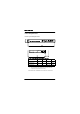
6WDUW XS DQG &RQILJXUDWLRQ 6WDWXV /('V TEST ESC ALT OK ACTIVE ALARM WARNING /('V RQ WKH FRQWURO SDQHO RI WKH %DVHEDQG 8QLW 7DEOH %DVHEDQG 8QLW /('V /(' ACTIVE 1 6WDWH )XQFWLRQ OFF The radio terminal is starting up or reconfiguring (INACTIVE state). Blinks 1 Hz The radio terminal is ready to transmit (STANDBY state). Blinks 15 Hz The radio terminal is transmitting (ACTIVE state). TEST Blinks 15 Hz The radio terminal is in TEST mode.
6WDUW XS DQG &RQILJXUDWLRQ 6WDUW XS DQG 6KXW GRZQ 6ZLWFKLQJ 21 WKH 5DGLR 7HUPLQDO 1. Make sure that the power supply feeding the BBU has an output voltage somewhere between 20 V and 72 V, any polarity. &$87,21 7KH VXSSO\ YROWDJH PXVW QRW H[FHHG 9 2. Connect the power cable to the BBU. 3. During start-up, the TEST LED blinks with 15 Hz.
6WDUW XS DQG &RQILJXUDWLRQ /RFDO 0DQDJHPHQW &RQQHFWLRQ Before connecting the radio terminal to local management equipment, in this case a PC, you must prepare the PC according to section 6HWWLQJ XS WKH 3& below. When this is done, connect the radio terminal locally by setting up a point-to-point network between the radio terminal and the PC using a static IP address. Refer to section &RQQHFWLQJ 'LUHFWO\ 8VLQJ 6WDWLF ,3 $GGUHVV on page 55.
6WDUW XS DQG &RQILJXUDWLRQ – Parity = 1RQH – Stop Bits = – Flow Control = 1RQH 6. Click 2.. 7. Save the session. 8. Exit the HyperTerminal program and close the connection. 9. Proceed to section ,QVWDOOLQJ 1XOO 0RGHP 'ULYHU below. ,QVWDOOLQJ 1XOO 0RGHP 'ULYHU The radio terminal is seen as a telephone modem by the PC. You must therefore install a null modem driver on your PC. 1. In the Windows 6WDUW menu, select 6HWWLQJV → &RQWURO SDQHO. 2. Double click on the 0RGHPV icon. 3. Select $GG . 4.
6WDUW XS DQG &RQILJXUDWLRQ 10. Select &20 or equivalent serial port that you want to connect the modem to. Click 1H[W !. 11. Click )LQLVK. 12. If the dialogue box “Modem properties” does not automatically appear, double click on the 0RGHP icon in the Control panel. 13. Click 3URSHUWLHV. 14. Under *HQHUDO, select Max speed = (other values are possible, refer to the Operation and Maintenance Manual (WLDM002)). 15. Under &RQQHFWLRQ, select Bits = , Parity = 1RQH, Stop bits = .
6WDUW XS DQG &RQILJXUDWLRQ &RQILJXULQJ 'LDOOLQJ 8S YLD WKH 6HULDO 3RUW The configuration for dialling up the radio terminal via the serial port depends on which operating system you are using on your PC; choose the correct alternative below. :LQGRZV 17 1. On your PC, double click on the 'LDO 8S 1HWZRUNLQJ icon located under the icon 0\ FRPSXWHU on the desktop, or under 0\ FRPSXWHU in the Explorer. 2. Enter 'LDO8S$05 as the Entry name in the dialogue box "New phonebook entry". Click 1H[W !. 3.
6WDUW XS DQG &RQILJXUDWLRQ 10. In the dialogue box "Dial Up Networking", select 0RUH → (GLW HQWU\ DQG PRGHP SURSHUWLHV . 11. Under %DVLF, make sure the $OOJRQ 0LFURZDYH 5DGLR modem is chosen in the box marked "Use:". 12. Click &RQILJXUH. 13. Select Initial Speed (bps) = (other values are possible, refer to the Operation and Maintenance Manual (WLDM002)). 14. Check (QDEOH KDUGZDUH IORZ FRQWURO. 15. Click 2.. 16. Click &ORVH. :LQGRZV 1.
6WDUW XS DQG &RQILJXUDWLRQ 7. Under &RQQHFWLRQ, select Data bits = , Parity = 1RQH, Stop bits = . Make sure that the box :DLW IRU GLDO WRQH is unchecked. 8. Click $GYDQFHG. Check 8VH IORZ FRQWURO, +DUGZDUH &76 . Click 2.. Click 1H[W !. 576 9. Leave the text box "Telephone number" empty. If the program requires that you enter a telephone number, you can enter any random number. This is of no importance for the function of the radio terminal modem. Click 1H[W !. 10. Click )LQLVK.
6WDUW XS DQG &RQILJXUDWLRQ &RQQHFWLQJ 'LUHFWO\ 8VLQJ 6WDWLF ,3 $GGUHVV Before connecting a PC to the radio terminal, make sure that the PC has been configured as described in section 6HWWLQJ XS WKH 3& on page 49. Then, do the following: 1. Make sure the radio terminal is switched ON. &RQQHFWLQJ WKH 3& WR WKH UDGLR WHUPLQDO YLD D VHULDO 3& FDEOH 2. Connect the PC to the radio terminal according to the figure above: a) Serial port (COM1 or equivalent) of the PC. b) Serial PC cable.
6WDUW XS DQG &RQILJXUDWLRQ 6. Allocate an IP address to the serial port LM/NMS 1 of the radio terminal by executing the command VHWLS LSDGGUHVV! where LSDGGUHVV! is the desired IP address. 7. Allocate a subnet mask to the serial port by executing the command VHWQP VXEQHWPDVN! where VXEQHWPDVN! is the desired subnet mask (default = ). 8. After you have changed the system settings according to step 9–10 above, you must restart the terminal for the changes to take effect.
6WDUW XS DQG &RQILJXUDWLRQ 'LDOOLQJ 8S YLD WKH 6HULDO 3RUW The procedure for dialling up the radio terminal via the serial port depends on which operating system you are using on your PC; choose the correct alternative below. :LQGRZV 17 1. On your PC, double click on the Dial Up Networking icon located under the icon for "My computer" on the desktop, or under "My computer" in the Explorer. 2. Select 'LDO8S$05. 3. A login dialogue box should now appear.
6WDUW XS DQG &RQILJXUDWLRQ 1RWH The Username and the Password are case sensitive. 4. Click &RQQHFW. 5. Proceed to section ,QLWLDO 5DGLR 7HUPLQDO &RQILJXUDWLRQ below. ,QLWLDO 5DGLR 7HUPLQDO &RQILJXUDWLRQ To get the radio terminal up and running, the minimum configuration you must perform is as follows: 1. Access the web pages of the radio terminal. Refer to section $FFHVVLQJ WKH :HE 3DJHV on page 60. 2. Supply the radio terminal with system information. Refer to section (GLWLQJ 6\VWHP ,QIRUPDWLRQ on pag
6WDUW XS DQG &RQILJXUDWLRQ 7UDIILF 5RXWLQJ LQ WKH ,QGRRU 8QLW Traffic Interface TIU Unit (1) TIU Port Port ternal Internal Baseband Unit (1) Cross Connect MUX Port MUX RF Sub-ch. RF Port RF Sub-ch.
6WDUW XS DQG &RQILJXUDWLRQ Before starting traffic configuration, a system administrator must have planned the radio terminal network concerning frequency bands, traffic load, and so on. 1RWH For further information on the traffic routing in the radio terminal, refer to the Operation and Maintenance Manual (WLDM002). $FFHVVLQJ WKH :HE 3DJHV 1. Start the web browser on your PC/management equipment. 2.
6WDUW XS DQG &RQILJXUDWLRQ (GLWLQJ 6\VWHP ,QIRUPDWLRQ Select 7HUPLQDO → ,GHQWLILFDWLRQ, and edit the following parameters: Terminal ID: (QWHU DQ ,' IRU WKH UDGLR WHUPLQDO Terminal location: (QWHU WKH QDPH RI WKH ORFDWLRQ IRU WKH UDGLR WHUPLQDO Contact: (QWHU QDPH DQG PHDQV RI FRQWDFW IRU WKH V\VWHP DGPLQLVWUDWRU RU WKH GHSDUWPHQW UHVSRQVLEOH IRU PDLQWDLQLQJ WKH UDGLR WHUPLQDO QHWZRUN Domain name: (QWHU D YDOLG IXOO\ TXDOLILHG GRPDLQ QDPH IRU WKH UDGLR WHUPLQDO 7KH GHIDXOW KRVWQDPH $05 PX
6WDUW XS DQG &RQILJXUDWLRQ &RQILJXULQJ WKH 5) &KDQQHO Select 7UDIILF → 5) &KDQQHO and edit the following parameters: Bandwidth 6HOHFW D EDQGZLGWK YDOXH RF frame format 6HOHFW DQ 5) IUDPH IRUPDW RF channel no (QWHU WKH 5) FKDQQHO QXPEHU RU 7; IUHTXHQF\ TX frequency (QWHU WKH FRUUHFW WUDQVPLWWHU IUHTXHQF\ RU 5) FKDQQHO QR TX mute 6HOHFW 1RUPDO IXQFWLRQ Output power (QWHU WKH GHVLUHG RXWSXW SRZHU OHYHO LQ VWHSV RI G%P ≤19 dBm for 37–40 GHz, ≤20 dBm for 21–30 GHz.
6WDUW XS DQG &RQILJXUDWLRQ &RQQHFWLQJ WKH 7UDIILF &KDQQHOV Select 7UDIILF → 7UDIILF &KDQQHO and edit the following parameters: 3RUWV Traffic channels from the TIU. These correspond to the traffic ports on the front of the terminal. WLDM001B )XQFWLRQ 6HOHFW KRZ WR FRQQHFW HDFK WUDIILF FKDQQHO • Not used: The traffic channel will not be used for any traffic. • Connect to MUX: The traffic channel will be connected to the MUX and transmitted by this radio terminal.
6WDUW XS DQG &RQILJXUDWLRQ &URVV FRQQHFWLQJ 7UDIILF &KDQQHOV Select 7UDIILF → %DFNSODQH &URVV FRQQHFW and edit the following parameters: /RFDO 3RUW TIU and MUX ports available for crossconnection. 5HPRWH 7HUPLQDO 5HPRWH 3RUW 6HOHFW WKH 6HOHFW WKH 7,8 RU EDFNSODQH 08; SRUW RQ WKH SDUWQHU WKDW \RX EDFNSODQH ZDQW WR FRQQHFW SDUWQHU WKDW \RX HDFK 7,8 DQG 08; ZDQW WR FRQQHFW SRUW WR HDFK 7,8 DQG 08; SRUW WR 1.
6WDUW XS DQG &RQILJXUDWLRQ (WKHUQHW 7UDIILF 3RUWV Select 7UDIILF → (WKHUQHW 7,8 and edit the following parameters: Maximum packet size 6HOHFW WKH PD[LPXP SDFNHW VL]H IRU WKH SRUWV Individual port setting: The maximum packet size is determined by the "Packet Size" for each individual port below. 6 kB packet size: The maximum packet size will be 6 kB. This setting overrides the "Packet Size" for each individual port below.
6WDUW XS DQG &RQILJXUDWLRQ XON threshold (QWHU WKH QXPEHU RI DOORFDWHG EXIIHUV WKDW PXVW EH SDVVHG EHORZ WR UHPRYH IORZ FRQWURO IURP D SRUW Default = 104 Address lookup algorithm 6HOHFW 0$& DGGUHVV ORRNXS DOJRULWKP Optimized for sequential MAC addresses Optimized for random MAC addresses 1. The actual number of buffers is truncated to the nearest lower multiple of 8. Port no The Ethernet traffic ports on the front of the terminal.
6WDUW XS DQG &RQILJXUDWLRQ Packet size 6HOHFW SDFNHW VL]H IRU HDFK SRUW E\WHV 1518: Used for most Ethernet types. 1536: Used for VLAN tagging. This setting may be overridden by "Maximum packet size" above. Port VLAN ID (QWHU D 9/$1 ,' IRU HDFK SRUW The VLAN ID is only applicable if "Ethernet VLAN tagging" is enabled above.
6WDUW XS DQG &RQILJXUDWLRQ 5HPRWH 0DQDJHPHQW &RQQHFWLRQ Connect the radio terminal remotely according to one of the following alternatives: • • For set-up of a TCP/IP network on an Ethernet LAN, refer to section &RQQHFWLQJ WR (WKHUQHW /$1 below. For set-up of a TCP/IP network via a modem, refer to section on page 70. &RQQHFWLQJ YLD 0RGHP • For set-up of a TCP/IP network via an ECC, refer to section on page 73. &RQQHFWLQJ YLD (&& &RQQHFWLQJ WR (WKHUQHW /$1 1.
6WDUW XS DQG &RQILJXUDWLRQ 4. Go to the web page "Network Interface Configuration" (1HWZRUN → ,QWHUIDFHV) and make sure that the status of the Ethernet port (10baseT) is set to "Up". 5. Exit the web browser and disconnect the serial PC cable between the local PC and the radio terminal. 6. Make sure the remote management equipment is connected to the Ethernet LAN network, or to another radio terminal connected to the Ethernet LAN network, and that it is set up to work properly in this environment.
6WDUW XS DQG &RQILJXUDWLRQ &RQQHFWLQJ YLD 0RGHP 1. Allocate an IP address to the serial port (MODEM/NMS 2) of the radio terminal in one of the following ways: – For set-up of a TCP/IP network on a modem connection using static IP addresses, allocate a static IP address, subnet mask and broadcast address to the serial port (MODEM/NMS 2). Refer to section $OORFDWLQJ 6WDWLF ,3 $GGUHVV on page 78.
6WDUW XS DQG &RQILJXUDWLRQ 4. Configure the modem AT commands for the serial port (MODEM/NMS 2) by selecting 1HWZRUN → 6HULDO ,QWHUIDFHV and clicking &RQILJXUH for the "Initialize sequence", "Dial sequence" or "Disconnect sequence".
6WDUW XS DQG &RQILJXUDWLRQ – CHAP secret (if CHAP is used); and – CHAP secret confirmation (if CHAP is used). 6. Perform a soft restart of the radio terminal for the changes to take effect: – Select 7HUPLQDO → 6WDWH &RQWURO and select Restart type = 6RIW. – Wait until the radio terminal is in STANDBY state. 7. Go to the web page "Address Configuration" (1HWZRUN → ,3 $GGUHVVHV ) to verify the changes above. 8.
6WDUW XS DQG &RQILJXUDWLRQ &RQQHFWLQJ YLD (&& 1. Allocate an IP address to the ECC port of the radio terminal in one of the following ways: – For set-up of a TCP/IP network on a ECC connection using static IP addresses, allocate a static IP address, subnet mask and broadcast address to the ECC port. Refer to section $OORFDWLQJ 6WDWLF ,3 $GGUHVV on page 78. – For set-up of a TCP/IP network on a ECC connection using dynamic IP addresses, configure the ECC port to use dynamic IP addresses.
6WDUW XS DQG &RQILJXUDWLRQ 3. Perform a soft restart of the radio terminal for the changes to take effect: – Select 7HUPLQDO → 6WDWH &RQWURO and select Restart type = 6RIW. – Wait until the radio terminal is in STANDBY state. 4. Go to the web page "Address Configuration" (1HWZRUN → ,3 $GGUHVVHV ) to verify the changes above. 5. Go to the web page "Network Interface Configuration" (1HWZRUN → ,QWHUIDFHV) and make sure that the status of the ECC port is set to "Up". 6.
6WDUW XS DQG &RQILJXUDWLRQ &RQQHFWLQJ YLD D &RPPRQ %DFNSODQH Connection of the radio terminal via a common backplane requires that it has been mounted in a 2U or 6U Magazine. 1. Allocate an IP address to the backplane port in question in one of the following ways: – For set-up of a TCP/IP network on a backplane connection using static IP addresses, allocate a static IP address, subnet mask and broadcast address to the backplane port. Refer to section $OORFDWLQJ 6WDWLF ,3 $GGUHVV on page 78.
6WDUW XS DQG &RQILJXUDWLRQ its environment. For further information, refer to the Operation and Maintenance Manual (WLDM002). 7. Proceed to section $QWHQQD $OLJQPHQW on page 80. 'DLV\ FKDLQLQJ 1. Allocate an IP address to the serial port (LM/NMS 1 or MODEM/NMS 2) of the radio terminal in one of the following ways: – For set-up of a TCP/IP network on a daisy chain using static IP addresses, allocate a static IP address, subnet mask and broadcast address to the serial port (LM/NMS 1 or MODEM/NMS 2).
6WDUW XS DQG &RQILJXUDWLRQ 4. Perform a soft restart of the radio terminal for the changes to take effect: – Select 7HUPLQDO → 6WDWH &RQWURO and select Restart type = 6RIW. – Wait until the radio terminal is in STANDBY state. 5. Go to the web page "Address Configuration" (1HWZRUN → ,3 $GGUHVVHV ) to verify the changes above. 6. Go to the web page "Network Interface Configuration" (1HWZRUN → ,QWHUIDFHV) and make sure that the status of the serial port (LM/NMS 1 or MODEM/NMS 2) is set to "Up". 7.
6WDUW XS DQG &RQILJXUDWLRQ $OORFDWLQJ 6WDWLF ,3 $GGUHVV Select 1HWZRUN → ,3 $GGUHVVHV and follow the link VWDWLF . Edit the following parameters for the interface in question: DGGUHVVHV KHUH ,QWHUIDFH Management network interface. $GGUHVV 6XEQHW PDVN %URDGFDVW DGGUHVV (QWHU WKH ,3 (QWHU WKH (QWHU WKH DGGUHVV IRU VXEQHW PDVN EURDGFDVW DGGUHVV WKH QHWZRUN IRU WKH QHWZRUN IRU WKH QHWZRUN LQWHUIDFH LQWHUIDFH LQWHUIDFH Default = 255.255.255.0 Default = 255.255.255.
6WDUW XS DQG &RQILJXUDWLRQ $OORFDWLQJ '\QDPLF ,3 $GGUHVV Select 1HWZRUN → '+&3 and edit the following parameter for the interface in question: ,QWHUIDFH Management network interface. 8VH '+&3 6HOHFW LI WKH LQWHUIDFH VKRXOG EH DOORFDWHG D G\QDPLF ,3 DGGUHVV IURP D '+&3 VHUYHU No: DHCP will not be used. Yes, send request on all interfaces: The DHCP request will be sent on all interfaces.
$QWHQQD $OLJQPHQW $QWHQQD $OLJQPHQW 7RROV 5HTXLUHG IRU $QWHQQD $OLJQPHQW • 17 mm torque wrench • Voltmeter (0–5V DC) with BNC adapter (the AGC contact on the RFU is of BNC socket type). 3UHSDUDWLRQV 1. Check that all relevant instructions in the preceding sections of this manual are completed for both installation sites before you start aligning the antennas. 2. Arrange for speech communication between the installation sites if possible. This will make it easier to align the antennas correctly.
$QWHQQD $OLJQPHQW $OLJQPHQW 3URFHGXUH When aligning the antennas, the AGC port on the RFU (BNC connector) is used to indicate the Received Signal Level (RSL). Use a standard multimeter with a BNC adapter to measure the AGC voltage. The AGC voltage is somewhere in the range 0–5V DC. 1RWH The alignment procedure should be performed for one antenna at a time. If the initial alignment error is large, however, you may need to begin by moving both antennas to achieve contact. 1.
$QWHQQD $OLJQPHQW – $]LPXWK ILQH WXQLQJ Loosen the two locking screws (A). Use the azimuth screw (B) to adjust the antenna. – (OHYDWLRQ ILQH WXQLQJ Loosen the two locking screws (C). Use the elevation screw (D) to adjust the antenna. 1RWH Do not loosen the locking screws too much. There should be a slight friction when aligning the antenna. 3. Use the torque wrench to secure the antenna position by tightening the locking screws for both azimuth and elevation.
,QVWDOODWLRQ 9HULILFDWLRQ DQG 7HVW ,QVWDOODWLRQ 9HULILFDWLRQ DQG 7HVW &KHFNLQJ 5) 3DWK 6WDWXV 1. Make sure that all relevant instructions in the preceding sections have been performed for both installation sites. 2. Make sure that your PC is connected to one of the radio terminals in the hop according to section /RFDO 0DQDJHPHQW &RQQHFWLRQ on page 49. 3. Follow the instructions in section $FFHVVLQJ WKH :HE 3DJHV on page 60 to access the web pages for one of the radio terminals. 4.
,QVWDOODWLRQ 9HULILFDWLRQ DQG 7HVW 3DUDPHWHU 6WDWXV Background Block Error during last second 1R Errored Second Rate Severely Errored Second Rate Background Block Error Rate RF Present Yes RF Measured Power Compare this value with the configured TX Output Power. 6. Repeat step 3–5 above for the radio terminal at the far end of the hop.
,QGH[ ,QGH[ 1XPHULFV 1 ft. antenna ...............................13 19" rack Installation Kit for...................17 mounting the Indoor Unit in ...25 2 ft. antenna ...............................13 26 pin D-SUB connector ............19 2U Magazine..............................18 Installation Kit for...................18 space requirements...............10 6U Magazine..............................18 Installation Kit for...................18 space requirements...............
,QGH[ common backplane connection .75 configuration local management .................49 radio terminal.........................58 remote management .............68 connecting the power cable .......48 connector 26 pin D-SUB for ext. I/O. 17, 31 37 pin D-SUB for traffic .........29 9 pin D-SUB for traffic ...........30 DC power ........................ 17, 32 mounting................................28 N type .............................. 33, 40 TNC ................................. 17, 33 contact person .
,QGH[ MAC address lookup .............66 packet size ...................... 65, 67 speed.....................................66 VLAN ............................... 65, 67 ETS 300 019 ........................ 12, 15 ETS 300 385 ........................ 11, 14 ETSI rack mounting kit...............18 external I/O connector.......... 17, 31 * grounding Antenna/RF Unit.............. 14, 40 indoor equipment...................11 Indoor Unit....................... 19, 27 M10 screw holes for ........
,QGH[ local management......................49 equipment..............................44 locking screw .............................37 login ...........................................60 0 M10 grounding screw holes . 14, 40 M10 screws................................37 M6 grounding lug ............11, 19, 27 magazine 2U..........................................18 2U Installation Kit ..................18 6U..........................................18 6U Installation Kit ..................18 mounting of.....
,QGH[ installation .............................34 requirements .........................13 outdoor radio cable grounding ..............................41 installation .............................40 maximum length ....................40 output power ..............................62 measured ..............................84 3 PAP............................................71 password....................................60 changing................................60 PC cable..................................
,QGH[ status.....................................83 RF frame format.........................62 RF subchannel cross connect....64 RFU, see Radio Frequency Unit RG213 cable ..............................40 RG214 cable ..............................40 RG400 cable ..............................33 RJ-45 connector.........................19 router..........................................45 RS-232 DCE.......................................19 DTE .......................................19 RSL .....................
,QGH[ TIU, see Traffic Interface Unit TNC connector................17, 19, 33 tools for indoor installation .............16 for outdoor installation ...........34 torque wrench ...................... 34 , 80 traffic channels configuration..........................63 connecting to backplane........63 connecting to MUX ................63 connectors....................... 29–30 Traffic Interface Unit............. 17, 20 balanced................................22 balanced, cables for ..............
,QGH[ WLDM001B