Revision 4.
Revision 4.
1. Packing Check List 4 2. Introduction 9 3. Antenna Mounting Precautions 20 4. Cable Routing 20 5. Safety 21 *Antenna colour and number of cables will differ with different versions 3 Revision 4.
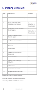
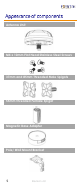
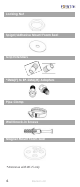
Item Description Quantity 1. *A-MIMO-0004 Antenna Only 1 2. M4 x 10mm Flat Head Stainless Steel Screws 4 (Attached to the antenna) 3. 37mm and 85mm Threaded Male Spigots 2 (1 Attached to the antenna) 4. 55mm Threaded Female Female Spigot 1 5. Magnetic Base Adapters 4 6. **Pole/ Wall Mount Bracket 1 7. Locking Nut 1 8. Spigot/Adhesive Mount Foam Seal 1 9. Grip Extenders 9*** 10. SMA(F) to RP-SMA (M) Adapters 4*** 11. Pipe Clamp 1 12. Wall Knock-in Screws 2 13.
Antenna Unit M4 x 10mm Flat Head Stainless Steel Screws 37mm and 85mm Threaded Male Spigots 55mm Threaded Female Spigot Magnetic Base Adapter Pole/ Wall Mount Bracket 5 Revision 4.
Locking Nut Spigot/Adhesive Mount Foam Seal Grip Extenders *SMA(F) to RP-SMA(M) Adapters Pipe Clamp Wall Knock-in Screws Magnet Mount Foam Seal *Antennas with Wi-Fi only 6 Revision 4.
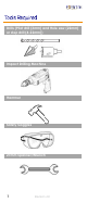
Drills (Pilot drill (3mm) and Hole saw (22mm) or step drill (4-22mm)) Impact Drilling Machine Hammer Safety Goggles 27mm Spanner/Wrench 7 Revision 4.
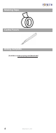
Masking Tape Centre Punch Drilling Template (Available on www.poynting.tech/downloads) 8 Revision 4.
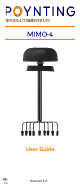
This User Guide provides information on the installation instructions of the Omni-directional antenna (A-MIMO-0004). Note: Ensure that all RF connections made outdoors are adequately waterproofed. Waterproof connector boots are recommended. Pole mount with supplied bracket and pipe clamp. • Lay the antenna out at the installation site. • Attach the bracket onto the base of the antenna using four flat head screws. • Secure the pipe clamp around the bracket and pole until the bracket is secured to the pole.
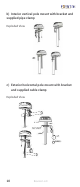
b) Interior vertical pole mount with bracket and supplied pipe clamp Exploded View c) Exterior horizontal pole mount with bracket and supplied cable clamp Exploded View 10 Revision 4.
d) Interior horizontal pole mount with bracket and supplied cable clamp Exploded View Wall mount with supplied bracket and wall knockin screws. • Select a suitable place for mounting the antenna. • Attach the bracket onto the base of the antenna using four flat head screws. • Using the wall mount bracket as a guide, mark two points to drill on the wall. Use a Ø6mm masonry drill bit to drill the marked points.
Note: Use a 6mm masonry drill bit to drill two holes into the wall. See the dimensions below. Exploded View 12 Revision 4.
Marine mount with supplied wall knock-in screws and marine bracket (BRKT-37- Not provided). • Select a suitable place for mounting the antenna. • Drill four holes into the surface for the cables and fasteners. See the dimensions below. • Mount the marine bracket (BRKT-37) onto the surface using suitable fasteners. • Remove the spigot mount seal. • Use the female threaded spigot joint to attach the antenna to the BRKT-37, with the cables being passed through the center. 13 Revision 4.
Exploded View 14 Revision 4.
Threaded spigot mounting. Use the Drill template below or download the 1:1 drill template from http://www.poynting.tech/downloads • Choose a flat mounting location which should be at least 50cm from heat sources, with a clear line of sight to the sky. • Once you have decided on the location and checked that there are no obstructions such as cables or channels below the mounting surface, for the fastening nut and cables to pass through, use the downloaded 1:1 drill template to mark the mounting location.
antenna to a surface structure of 70mm thickness or less. Securing the antenna • Fasten the required spigot with the Flat head screws. • Clean the plastic surface of the antenna base and threaded spigot. • Peel off the top wax paper layer from the spigot mount adhesive foam seal and stick the foam seal to the antenna surface. • Carefully slide the cable through the drilled hole. • Peel off the second wax paper layer and firmly press the antenna down onto the surface.
Revision 4.
Adhesive mounting • Clean the entire surface on which you plan to stick the antenna. Alcohol wipes can be used to remove oil and dirt from the surface. • Remove the nut, foam seal, flat head screws and short spigot from antenna. • Put the foam seal back through the cables and towards the base of the antenna. • Peel off the wax paper layer and stick the adhesive mount foam seal to the bottom antenna surface. • Peel off the second wax paper layer and firmly press the antenna down onto the surface.
Optional magnetic mount with magnetic base kit (A-MBK-003 -Not Provided). For temporary and low mobility installations. • Clean the entire surface on which you plan to place the antenna. Alcohol wipes can be used to remove oil and dirt from the surface. • Remove nut, spigot mount foam seal and spigot from antenna. • Secure the magnetic base adapters and magnets from the MBK-3 to the antenna using the screws provided with the MBK-3.
• Place the antenna at the highest point possible and ensure that there are not any surrounding obstructions to the antenna. • In order to avoid communication interference, ensure that the antenna is placed at least 0.5m away from other antennas and metal objects. • Avoid installing the antenna near a chimney, as the smoke and soot emitted by the chimney can obstruct the signal level achieved by the antenna. • Install the antenna away from heat sources and flammable gases.
When handling the antenna cables, it is essential you follow these basic rules: • • • Never pull on the cable connectors; pull only on the cable. Cover connectors with insulation tape before threading them through a hole. Tighten the connectors and ensure that the cables don’t rattle loose. • If you are installing an antenna for the first time or unsure about how to install your antenna, obtain the help of a professional installer.
jewelry or clothing is secured and tie back long hair as they can get caught in moving parts during installation. 5. If the antenna assembly starts to fall, get away from it and let it fall to avoid harming yourself. • When drilling remember: 1. Use safety goggles when drilling the holes. 2. Avoid using bits that are dull, bent or damaged. 3. Be aware of where your fingers are in relation to the drill bit when using the drilling machine. 4.
South Africa USA USA Europe Unit 4, N1 Industrial Park Landmarks Ave Samrand, 0157 South Africa Tel: +27 12 657 0050 info@poynting.tech 1804 1804 Owen Owen Court, Court, Suite Suite 104, 104, Mansfield, Mansfield, TX 76063 76063 TX Tel: +1 +1 817 817 533-8130 533-8130 Tel: sales-us@poynting.tech sales-us@poynting.tech Kronstadler Straße 4, 81677 München Germany Tel: +49 89 2080 265 38 Mob.: +49 176 529 733 50 sales-europe@poynting.tech 23 Revision 4.