PIECAL 820 Multifunction Process Calibrator mA • V •TC • Ω • RTD • Hz Operating Instructions Practical Instrument Electronics 82 East Main Street Suite 3.14 • Webster, NY 14580 USA Tel: 585.872.9350 • Fax: 585.872.2638 • sales@piecal.com • www.piecal.
Contents General Operations Carrying Case, Boot & Changing Batteries................. 2 Storing EZ-CHECK Outputs & Connections............... 3 Basic Operation Switches & Knobs....................................................... 4 Double Click Menus.................................................... 6 Stepping & Ramping................................................... 8 Auto Off....................................................................... 8 Backlight..........................................
General Information Technician friendly operation The unique and intuitive EZ-DIAL Double Click Menu makes it easier to setup than other multifunction calibrators. Uses the same menus as the single function PIECAL Evolution Calibrators. Use it as a milliamp and voltage calibrator Source 0 to 24.00 mA, 0 to 10.25 V dc & -10.00 to 80.00 mV Read to 24.00 mA, 60.0 V dc and and -10.00 to 80.00 mV Simulate 2-Wire Transmitters & Power up transmitters & loops Calibrate in temperature with 0.
Operating Instructions FIELD & BENCH USE PIECAL 820 comes with a carrying case designed for handsfree operation and a rubber boot with a built-in tilt stand. The PIECAL 820 is held in the case by elastic straps for use with the carrying case open. The tilt stand is easily raised by pulling the stand until it locks into place. CHANGING BATTERIES Low battery is indicated by “BAT” on the display. Approximately one to four hours of typical operation remain before the PIECAL 820 will automatically turn off.
Operating Instructions STORING HI and LO EZ-CHECK Source Outputs Speed up your calibration by storing Span & Zero output setting for instant recall with the EZ-CHECK switch. 1) Store your high (SPAN) output temperature by moving the EZ-CHECK switch to the HI position and turning the EZ-Dial knob until the desired output value is on the display. Press and hold the EZ-Dial knob until STORED appears to store the value. Release the EZ-Dial knob.
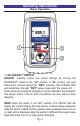
Operating Instructions Basic Operation SOURCE HI MAX SET READ LO MIN READ q EZ-CHECK™ SWITCH SOURCE: Instantly output two preset settings by moving the EZ-CHECK™ switch to the “LO” position or “HI” position. For fast three point checks select the “SET” position. The PIECAL 820 will remember the last “SET” value, even with the power off. These values can easily be changed to suit the calibration requirements. The values stored in the HI and LO positions are also used for Auto Stepping.
Operating Instructions Basic Operation w SOURCE/OFF/READ Switch Select “SOURCE” to output mA, V, T/C, Ohms, RTD or frequency. Select “READ” to read mA, V, T/C, Ohms, RTD or frequency. e EZ-DIAL™ KNOB SOURCE: Turn the knob to adjust the output level. Turn clockwise to increase the output, counter clockwise to decrease the output in one least significant digit steps at a time. Push down and turn the EZ-DIAL knob for faster dialing.
Operating Instructions Double Click Menus Double click the EZ-DIAL knob to access the Double Click Menus to select each function and the options for each function. Available choices are shown in grey.
Operating Instructions Double Click Menus Source & Read Thermocouples > EXIT FUNCTION UNITS T/C TYPE COLD JUNC T/C °C °F J K ET R S B N L U G C D P ON Source RTD > EXIT FUNCTION RTD UNITS °C °F RTD Pt 100 a=3850 [* RTD Types] WIRE MODE 234W Read RTD > EXIT FUNCTION RTD UNITS °C °F RTD Pt 100 a=3850 [* RTD Types] WIRE MODE 3W 2W 4W * RTD Types: Pt 100 a=3850, a=3902, a=3916, a=3926 Pt 1000 a=3850; Cu 10 a=4274, Cu 50 a=4280 Ni 120 a=6720, Ni 110 a=5801 Sourc
Operating Instructions Double Click Menu - STEPPING, AUTO OFF & BACKLIGHT To change the Automatic Stepping settings Double click the e DIAL KNOB at any time the unit is on and the following typical display (will be different for each FUNCTION) will appear for 15 seconds: > EXIT FUNCTION mA MODE SOURCE UNITS mA HART 250Ω ON Turn the e DIAL KNOB to move to the second menu page. Turn the e DIAL KNOB to move through the menu.
Operating Instructions Double Click Menu - STEPPING, AUTO OFF & BACKLIGHT STEPS - pressing the knob will cycle through 2, 3, 5, 11 and RAMP. The endpoints of the steps or ramp are based on the values stored in the HI and LO EZ-CHECK outputs. 2 steps will automatically switch between the values stored in the HI & LO EZ-CHECK (0 & 100%). 3 steps between the HI, Midpoint and LO EZ-CHECK (0, 50 & 100%). 5 steps between the HI and LO EZ-CHECK in 25% increments (0, 25, 50, 75 & 100%).
mA SOURCE/ % SOURCE (Percent of 4 to 20 mA) Choose this function to provide an output from 0.00 to 24.00 milliamps. The compliance voltage is a nominal 24 VDC to provide the driving power to your milliamp receivers. Move the power switch w to SOURCE then Double Click the EZ-DIAL knob to get into the Double Click Menu. Turn the knob to scroll through the settings and press the knob to make your selection. Select mA for the FUNCTION and SOURCE for the MODE.
2 Wire SIM mA, 2 Wire SIM % (Percent of 4 to 20 mA) Choose this function to simulate a 2 Wire Transmitter output from 0.00 to 24.00 milliamps. Operates in loops with power supply voltages from 2 to 60 VDC. Move the power switch w to SOURCE then Double Click the EZ-DIAL knob to get into the Double Click Menu. Turn the knob to scroll through the settings and press the knob to make your selection. Select mA for the FUNCTION and 2W SIM for the MODE.
READ mA, READ % (Percent of 4 to 20 mA) Choose this function to measure from 0.00 to 24.00 milliamps or -25.0 to 125.0%. Move the power switch w to READ then Double Click the EZ-DIAL knob to get into the Double Click Menu. Turn the knob e to scroll through the settings and press the knob to make your selection. Select mA for the FUNCTION and READ for the MODE. Choose either mA or % and whether you need the 250Ω HART resistor active in the loop.
Power/Measure mA, Power/Measure % (Percent of 4 to 20 mA) Choose this function to simultaneously supply power to a 2 Wire Transmitter while displaying the 4 to 20 mA output of the transmitter. Move the power switch w to READ then Double Click the EZ-DIAL knob to get into the Double Click Menu. Turn the knob e to scroll through the settings and press the knob to make your selection. Select mA for the FUNCTION and PWR MEAS for the MODE.
mV/V SOURCE Choose this function to provide an output from 0.00 to 80.00 mV or from 0.00 to 10.25 V. The source current is a nominal 24 mA to provide the driving power to your voltage receivers. Move the power switch w to SOURCE then Double Click the EZ-DIAL knob to get into the Double Click Menu. Turn the knob to scroll through the settings and press the knob to make your selection. Select V for the FUNCTION and 10V or 80 mV for the RANGE.
Read mV/V Choose this function to measure from 0.00 to 80.00 millivolts, 0.00 to 10.25 V dc or 0.0 to 60.0 V dc. Move the power switch w to READ then Double Click the EZ-DIAL knob to get into the Double Click Menu. Turn the knob to scroll through the settings and press the knob to make your selection. Select V for the FUNCTION and 10V, 60V or 80 mV for the RANGE. Connect the red input lead (+) of the PIECAL 820 to the more positive point of the break and the black input to the more negative point.
Thermocouple Source Choose this function to provide a simulated thermocouple signal into controllers, temperature transmitters, indicators or any input devices that measure thermocouple sensors. Move the power switch w to SOURCE then Double Click the EZ-DIAL knob to get into the Double Click Menu. Turn the knob to scroll through the settings and press the knob to make your selection.
Read Thermocouple Sensors Choose this function to measure temperatures with a thermocouple probe or sensor. Move the power switch w to READ then Double Click the EZ-DIAL knob to get into the Double Click Menu. Turn the knob to scroll through the settings and press the knob to make your selection. Select T/C for the FUNCTION, °F or °C for the UNITS, T/C Type (J, K, T, E, R, S, B, N, G, C, D, L (J-DIN), U (T-DIN) or P (Platinel II) and COLD JUNC ON or OFF (ON is the default).
Resistance Source Choose this function to provide a simulated resistance into any device that measures resistance. Move the power switch w to SOURCE then Double Click the EZ-DIAL knob to get into the Double Click Menu. Turn the knob to scroll through the settings and press the knob to make your selection. Select OHMS for the FUNCTION, 400Ω or 4000Ω for the RANGE. Disconnect all sensor wires from the devices to be calibrated and connect the PIECAL 820 to the inputs of the device using 2, 3 or 4 wires.
Read Resistance & Check Continuity Choose this function to measure resistance or check continuity. Move the power switch w to READ then Double Click the EZ-DIAL knob to get into the Double Click Menu. Turn the knob to scroll through the settings and press the knob to make your selection. Select OHMS for the FUNCTION, 400Ω, 4000Ω or Continuity for the RANGE. You must also select the WIRE MODE for 2W, 3W or 4W to match the 2, 3 or 4 wires being used to measure resistance. For continuity the only choice is 2W.
RTD Source Choose this function to provide a simulated RTD signal into controllers, temperature transmitters, indicators or any input devices that measure RTD sensors. Move the power switch w to SOURCE then Double Click the EZ-DIAL knob to get into the Double Click Menu. Turn the knob to scroll through the settings and press the knob to make your selection. Select RTD for the FUNCTION, °F or °C for the UNITS and RTD (Choose from one of Platinum 100Ω, or 1000Ω, Copper 10Ω or 50Ω, Nickel 120Ω or 110Ω curves).
Read RTD Sensors Choose this function to measure temperatures with an RTD probe or sensor. Move the power switch w to READ then Double Click the EZ-DIAL knob to get into the Double Click Menu. Turn the knob to scroll through the settings and press the knob to make your selection. Select RTD for the FUNCTION, °F or °C for the UNITS and RTD (Choose from one of Platinum 100Ω, or 1000Ω, Copper 10Ω or 50Ω, Nickel 120Ω or 110Ω curves). Note: Pt 100Ω 3850 is the most common RTD type.
Frequency Source Choose this function to provide a frequency signal into any input devices that measure frequency. Move the power switch w to SOURCE then Double Click the EZ-DIAL knob to get into the Double Click Menu. Turn the knob to scroll through the settings and press the knob to make your selection. Select FREQ for the FUNCTION and 20KHZ, 10000HZ, 1000HZ or 2000CPM for the RANGE.
Read Frequency Choose this function to count frequency. Move the power switch w to READ then Double Click the EZ-DIAL knob to get into the Double Click Menu. Turn the knob to scroll through the settings and press the knob to make your selection. Select FREQ for the FUNCTION and 20KHZ, 10000HZ, 1000HZ or 2000CPM for the RANGE. Disconnect all input wires from the devices to be calibrated and connect the PIECAL 820 to the output of the device matching polarity.
Specifications General Operating Temp Range -20 to 60 °C (-5 to 140 °F) Storage Temp Range -30 to 60 °C (-22 to 140 °F) Temperature effect ≤ ± 0.01 %/°C of Full Scale Relative Humidity Range 10 % ≤RH ≤90 % (0 to 35 °C), Non-condensing 10 % ≤RH≤ 70 % (35 to 60 °C), Non-condensing Normal Mode Rejection 50/60 Hz, 50 dB Common Mode Rejection 50/60 Hz, 120 dB Noise ≤ ± ½ Least Significant Digit from 0.1 to 10 Hz Size 5.63x3.00x1.60” 143x76x41mm (LxWxH) Weight 12.1 ounces, 0.
Specifications Read mA Ranges and Resolution 0.00 to 24.00 mA or -25.0 to 125.0% of 4-20 mA Accuracy ≤ ± (0.03 % of Full Scale) Voltage burden ≤ 2V at 24 mA Overload/Current limit protection 25 mA nominal Source mA / Power & Measure Two Wire Transmitters Ranges and Resolution 0.00 to 24.00 mA or -25.0 to 125.0% of 4-20 mA Accuracy ≤ ± (0.03 % of Full Scale) Loop compliance voltage ≥ 24 DCV @ 20.
Specifications DC Voltage Read Range and Resolution -10.00 to 80.00 mV, 0 to 10.25 V, 0.0 to 60.0 V Accuracy ≤ ± 0.03 % of Full Scale Input resistance ≥ 1 MΩ Source V dc Ranges and Resolution -10.00 to 80.00 mV, 0 to 10.25 V Accuracy ≤ ± (0.03 % of Full Scale) Source Current ≥ 24 mA Sink Current > 16 mA Output Impedance < 1 Ohm Short Circuit Duration Infinite Thermocouple Source Accuracy ±(0.03% of Full Scale) [Note: Full Scale is 80.
Specifications Thermocouple Read Accuracy & Cold Junction Compensation Same as Thermocouple Source Input Impedance > 1 Megohms Open TC Threshold; Pulse 10K Ohms; <5 µamp pulse for 300 milliseconds (nominal) RTD, OHMS and Continuity Read Resistance Ranges 0.0 to 401.0, 0 to 4010 Ohms Accuracy ±(0.03% of Full Scale + 0.075 Ohms) Excitation Current 1.0 mA to 401 Ohms, 0.6 mA to 4010 Ohms (nominal) Continuity 0.0 to 401.0 Ohms; Beeps from 0.0 to 100.
Specifications Frequency Source Ranges 1 to 2000 CPM, 0.01 to 999.99 Hz, 0.1 to 9999.9 Hz, 0.001 to 20.000 kHz Accuracy ±(0.03% of Full Scale) Output Waveform Square Wave, Zero Crossing -1.
Thermocouple Ranges & Accuracies Based on ±(0.03% of 80 mV) T/C Degrees C Range °C Degrees F Range °F J -200.0 to -150.0 ±1.2° -328.0 to -238.0 ±2.0° -150.0 to -50.0 ±0.7° -238.0 to -58.0 ±1.3° -50.0 to 100.0 ±0.5° -58.0 to 212.0 ±0.9° 100.0 to 1200.0 ±0.4° 212.0 to 2192.0 ±0.8° -230.0 to -150.0 ±2.6° -382.0 to -238.0 ±4.7° -150.0 to 0.0 ±1.0° -238.0 to 32.0 ±1.8° K T E R 0.0 to 1100.0 ±0.6° 32.0 to 2012.0 ±1.1° 1100.0 to 1371.1 ±0.7° 2012.0 to 2500.0 ±1.2° -260.
Thermocouple Ranges & Accuracies Based on ±(0.03% of 80 mV) T/C Degrees C Range °C Degrees F Range °F S -18.3 to 50.0 ±6.1° -1.0 to 122.0 ±10.9° 50.0 to 300.0 ±3.7° 122.0 to 572.0 ±6.6° 300.0 to 600.0 ±2.6° 572.0 to 1112.0 ±4.7° 600.0 to 1767.8 ±2.3° 1112.0 to 3214.0 ±4.2° 315.6 to 600.0 ±7.9° 600.0 to 1122.0 ±14.2° 600.0 to 1050.0 ±4.0° 1122.0 to 1922.0 ±7.3° 1050.0 to 1400.0 ±2.5° 1922.0 to 2552.0 ±4.6° 1400.0 to 1820.0 ±2.1° 2552.0 to 3308.0 ±3.8° -230.0 to 0.0 ±4.
Thermocouple Ranges & Accuracies Based on ±(0.03% of 80 mV) T/C Degrees C Range °C Degrees F Range °F D -1.1 to 200.0 ±1.8° 30.0 to 392.0 ±3.2° P 200.0 to 1350.0 ±1.4° 392.0 to 2462.0 ±2.6° 1350.0 to 2000.0 ±1.9° 1742.0 to 3632.0 ±3.4° 2000.0 to 2320.0 ±2.6° 3632.0 to 4208.0 ±4.7° -200.0 to 0.0 ±2.1° -328.0 to 32.0 ±3.8° 0.0 to 150.0 ±0.8° 32.0 to 302.0 ±1.5° 150.0 to 1100.0 ±0.6° 302.0 to 2012.0 ±1.1° 1100.0 to 1395.0 ±0.8° 2012.0 to 2543.0 ±1.5° L J-DIN -200.
RTD Ranges & Accuracies Based on ±(0.03% of 400Ω) / Pt 1000Ω Based on ±(0.03% of 4000Ω) RTD Type Degrees C Range °C Degrees F Range °F Pt 100 Ohm DIN/IEC/JIS 1989 1.3850 (ITS-90) -200.0 to 120.0 120.0 to 430.0 430.0 to 850.0 ±0.5° ±0.6° ±0.7° -328.0 to 248.0 248.0 to 806.0 806.0 to 1562.0 ±0.9° ±1.0° ±1.2° Pt 100 Ohm (Burns) 1.3902 -195.6 to 160.0 160.0 to 460.0 460.0 to 648.9 ±0.5° ±0.6° ±0.7° -320.0 to 320.0 320.0 to 860.0 860.0 to 1200.0 ±0.9° ±1.0° ±1.2° Pt 100 Ohm (Old JIS 1981) 1.
Warranty Our equipment is warranted against defective material and workmanship (excluding batteries) for a period of three years from the date of shipment. Claims under warranty can be made by returning the equipment prepaid to our factory. The equipment will be repaired, replaced or adjusted at our option. The liability of Practical Instrument Electronics (PIE) is restricted to that given under our warranty.
Additional Information PIE Calibrators are manufactured in the USA. This product is calibrated on equipment traceable to NIST and includes a Certificate of Calibration. Test Data is available for an additional charge. Practical Instrument Electronics recommends a calibration interval of one year. Contact your local representative for recalibration and repair services. Practical Instrument Electronics 82 East Main Street Suite 3.14 Webster, NY 14580 USA Tel: 585.872.9350 • Fax: 585.872.2638 sales@piecal.