
User's Manual


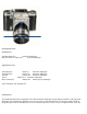
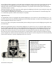

Table Of Contents
- Praktisix Manual
- Instructions for use
- Inserting the film
- Setting the film speed indicator
- The finder hood
- The magnifier
- The sports finder
- The pentaprism
- Focusing
- The rangefinder lens
- Exchanging field lenses
- Setting the diaphragm
- The shutter
- Setting the shutter speeds
- The rapid wind lever
- Locking the release nut
- Flash synchronization
- Removing the film
- Exchanging lenses
- Interchangeable lenses
- Standard lenses
- Supplementary lenses
- Standard lenses
- Supplementary lenses
- Accessories for close‑up work
Swing the rapid wind lever around to its stop and move back to its original position. The shutter is thus cocked, the
film is advanced by one frame, the diaphragm set to its widest aperture, the exposure counter switched to the next
number and, the mirror having been set, the path is open the light rays to reach the ground glass.
The delayed action
Swing winding lever (4) of the delayed-action mechanism through 90 degrees and actuate release knob (3). The
mechanism runs for approximately 10 seconds and may be employed with all shutter speeds.
The delayed-action lever remains in end the position only if the shutter has been cocked beforehand.
Locking the release nut
Lock the release mechanism by turning the lower milled ring (14) on release knob (3) anticlockwise as far as it will
go. (The red dot must be at the top.) Inadvertent tripping of the shutter is thus impossible. The shutter release
mechanism is freed by turning the ring back again.
Flash synchronization
Synchronization for electronic flash and bulbs is affected by means of the X-contact on the lower part of the camera
front, next to the tripod Bush (5).
For electronic flash, move the shutter speed setting disk (11) to the speed marked by the flash arrow. Longer speeds
may also be used. For short burning bulbs set a shutter speed of 1/15 of a second and for all the longer duration 1/8
of the second. The correct diaphragm setting is found by dividing the guide number of the flash by the flash-to
subject distance figure.
Removing the film
Swing the rapid wind lever around once as far as it will go and continue winding up the paper backing by small
rocking movements until actuating the lever becomes noticeably easier. Only then open the camera back. Fasten the
gumstrip and remove the spool with the exposed film. Films can be exchanged in daylight.
Exchanging lenses
Turn milled ring (15) of the bayonet fitting anti-clockwise until it stops. The lens is now unlocked and can be
removed from the camera. The red mark on the scale of the lens to be inserted must be at the top, and the screw, or
pin, on the inner edge of the lens mount has to engage in the recess of the bayonet fitting in the camera (see arrow in
illustration). To fix the lens tighten milled ring (15) by clockwise movement.