
Install Guide

TECNOELETTRA s.r.l. via D.Vioni n.5 – 42016 S. Rocco - Guastalla (RE) Tel.+39.0522.832004 Fax.+39.0522.832012
mail: info@tecnoelettra.it web: www.tecnoelettra.it
Cod. Doc. AT206-origineel E 1 / 4
WARNING! Check that the product delivered exactly corresponds to the ordered
one.
Installation
General information
Power electrical connections
AT206 / AT206B “Quick installation guide” UK
Description of the data shown on the label
In = nominal current
Imax = maximum rated current
KA = maximum breaking current against short circuit
Hz = frequency
KVA = apparent power (calculated at cos fi 0,8)
KW = active power
HP = horse power
V~ = maximum use voltage of the primaries
Vaux = maximum voltage of the auxiliary circuits
IP = degree of protection against external agents
Kg = approximate weight
Dim = dimensions Height x Width x Depth
Ser.n = serial number
Model = product code
TECHNICAL FEATURES
Nominal voltage battery............................................. 12Vdc
Maximum rated current ............................................250mA
Maximum rated power .................................................. 3W
Operating range ................................................ 1017VDC
Nominal voltage generator/mains ........... 100 ÷ 265Vac L-N
Measuring range voltage appearing…………..50 ÷ 450Vac
Frequency range .................................................. 45 65Hz
Degree of protection front board ..................................IP65
Degree of protection of switchboard .............................IP20
Operating temperature ..................................... -20 +50°C
Storage temperature ........................................ -30 +70°C
Maximum rated humidity ............................................ 90%
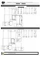
Single-phase systems connections 2P
sistemi monofase 2P
Three-phase systems connections 4P
GENERATOR
MAINS
L N
L N
L N
LOAD
GENERATOR
MAINS
L1 L2 L3 N
LOAD
L1 L2 L3 N
L1 L2 L3 N
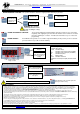
Cables sections
Single-phase system 2P (max 5m)
I max min. sec. max sec.
40A 2x 4mm² 2x 6mm²
51A 2x 4mm² 2x 6mm²
72A 2x 6mm² 2x 10mm²
89A 2x 10mm² 2x 16mm²
96A 2x 10mm² 2x 16mm²
Three-phase system 4P (max 5m)
I max min. sec. max. sec.
25A 1x 4mm² 1x 6mm²
32A 1x 6mm² 1x 6mm²
45A 1x 10mm² 1x 10mm²
56A 1x 16mm² 1x 16mm²
60A 1x 16mm² 1x 16mm²
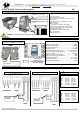
Ø= 6mm
245mm
Free space of
aeration reason =
min. 10cm all around
the switchboard
Drilling template
(use the two screw anchor provided )
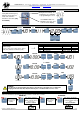
CT only if
available
CT only if
available
F1 = F6,3A Protection for the
auxiliary battery circuits 12Vdc
F2 = F2A Protection mains contactor
F3 = F2A Protection generator
contactor
Internal Batterycharger with fuse
FCB = F500mA