
Installation Instructions

Multi-Piece Sectional Product
Installation Instructions
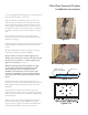
5. In the installation location, the drain opening in the oor
should have a 6” core for the drain pipe, and a 10” x 10” x 1/2”
deep recess in the sub oor. (The drain core must be blocked
when lled with Thin-Set). The 10” x 10” x 1/2” deep recess is
required to to assure proper drainage. See Detail of Drain Core
Area
6.Check the outside of the package for visible shipping damage.
If damage is noted, contact your supplier before proceeding
with the installation.
7. Locate accessories if any were ordered. They will be
packaged in the pan box. Remove those and store them in a
safe location for easy retrieval.
8. Identify each package and its contents. The label on the box
is clearly marked indicating a shower pan and wall panels.
INSTALLATION INSTRUCTIONS
1. Prepare the installation area by sweeping the area
completely clean.
2. Framing pocket must be sized according to the information
provided in the Framing Diagram. It is recommended that
the front studs at each side be doubled for added strength.
Framing must be extremely square and plumb in order to
accomplish a successful installation.
3. Install hot and cold water supply lines with the control valve.
Mount to the framing.
4. It is extremely important that the oor area intended for
the installation be at and level. Any areas over 1/8” out-of-
level will prevent the installation from being successful. If an
area out more than 1/8” is found, oat the oor area with a
oor leveling compound. This material must be placed and
cured (dry) before proceeding with the shower installation.
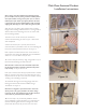
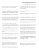
5. A special note: During handling and transport, the product
may be slightly bent. It is very important that the seam side of
each wall, and the threshold of the pan does not have any bow or
bend. This product is engineered with materials that allow for the
sections to be pressed back to the normal and straight factory
form that is intended.
As each section is removed from the packaging, use a straight
edge to check the straightness of the wall sections and of the
threshold. An example of checking the threshold is illustrated
in Figure 2A. Check all the parts, and if not straight, follow the
6.
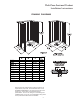
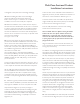
Carefully measure the framing pocket to assure it is of
proper size for the unit to be installed. Refer to
dimensional information in the Framing Diagrams on
Page 3, Figure 1.
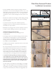
5.
A special note: During handling and transport,
the product may be slightly bent. It is very important
that the seam side of each wall, and the threshold of the
pan does not have any bow or bend. This product is
engineered with materials that allow for the sections to be
pressed back to the normal and straight factory form that
is intended.
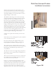
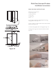
7.
Check the framing pocket for square. Check to assure
the vertical studs are plumb. To have tight seams where
the parts meet, it is very important that the framing pocket
be exceptionally square and plumb.
Check for square by holding a measuring tape from the
back left corner to the front right corner, as shown in
Figure 4. Repeat for the other side. If both dimensions are
the same, the framing is square. Adjust if necessary.
As each section is removed from the packaging, use a
straight edge to check the straightness of the wall sections
and of the threshold. An example of checking the threshold
is illustrated in Figure 2A. Check all the parts, and if not
straight, follow the procedures outlined below to bring the
parts back into the intended condition.
In the event they are not straight to 1/16”, pressure can be
applied to the top side of the material. This can be
accomplished by placing blocks under the two extreme
corners.
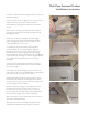
Always place a soft rag on the finished surface where it
contacts the wood blocks, and under your feet to avoid
damaging the finish.
Gently step on this area and allow your body weight
(Up to 250 pounds), to flex the material back straight.
Confirm straightness, repeat if necessary until +/- 1/16”
is accomplished. (Figures 2B and 2C)
Once the dry fit has been done and the fit confirmed,
disassemble the components. Resume step 5 and follow
each step carefully.
A complete dry fit for the shower base and walls is
recommended. A dry fit in this instance is defined as
securing the sections to the studs with no silicone and
minimal screws to confirm a good fit, and the framing
accommodates the sections. To achieve a dry fit
installation, proceed with steps 6 through 23 without using
the silicone, floor adhesive and minimal screws to secure
to the framework.
4
Figure 3
Figure 4
Figure 2C
Figure 2B
Figure 2A