Instruction Manual HiTempIR Heater Model 5209 November, 2008 Another quality product from: 7128 Shady Oak Road • Eden Prairie, MN 55344 (952) 949-9009 Fax (952) 949-9559 www.researchinc.com sales@researchinc.
Contents Contents Contents .................................................................................................................................. 1 1. Introduction ............................................................................................................................. 1 General Description .................................................................................................................... 1 Heater Module ......................................................
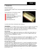
Section 1 1. Introduction General Description The Model 5209 Hi-TempIR® heater is designed to provide high-intensity intensity infrared heat onto localized areas.
Heater Safety An integrated thermostat is mounted to the backside of the aluminum reflector. The thermostat is wired to the pinned connector with corresponding wiring residing in the removable electrical cable. When wired into an appropriately designed power source, the normally closed thermostat will open upon reaching an overheat condition preventing electrical power from reaching the heater. The thermostat will close once the heater cools down to a safe operating temperature.
Standard Features The design and functionality of the Model 5209 supplies a variety of features and related benefits: Rapid Response The quartz halogen lamps heat up and cool down instantly in response to power control signals. They reach 90 percent of full operating temperature within three seconds of a cold start. The radiant energy dissipates to ten percent five seconds after the power supply is disconnected.
Section 2 2. Safety GENERAL The Model 5209 heater is designed for safe operation. Nevertheless, installation, maintenance, and operation of the heater can be dangerous for a careless operator or maintenance person. For your safety and the safety of others, read the instructions in this Instruction Manual and follow these safety practices to help prevent accident or injury.
!WARNING! NEVER place hands under or in front of the heating elements. ALWAYS allow heating element to cool at least three minutes before touching the lamps or adjacent parts. Electrical Safety There is danger of electrical shock when servicing the heater. !CAUTION! Observe all applicable local and national electrical codes and a safe electrical ground system is installed before attempting to operate the heater. Refer to the Section 5 for proper installation procedures.
Section 3 3. Installation Unpack and Check for Damage Remove the model 5209 heater from its shipping container and associated packaging. Check the unit for any potential damage due to shipping. In the unlikely event damage has occurred, keep all shipping containers and materials in order to file a damage claim with the shipping company responsible for shipping the unit.
Figure 3-2 7
Section 4 4. Operating Instructions Heater Cooling Connections Each Model 5209 is designed with three ‘quick-disconnect’ fittings protruding from the top of the heater cover. The two fittings located at the outer ends of the heater are the inlet/outlet cooling water ports. The single fitting located at the center of the heater is the cooling air inlet port. All three fittings accept ½-inch outer-diameter flexible nylon tubing. A 30-ft. (9.
Electrical Connections Each of the six T3 lamps of the Model 5209 is electrically wired to intermediate, individual terminal blocks within the heater. In turn, each terminal block along with the heater safety thermostat and heater grounding wires are wired to a 19-pin connector mounted to the heater cover (see Figure 4-2). Figure 4-2 Each heater is supplied with either a 10- or 20- ft.
Figure 4-3 As shown in Figure 4-4, the junction box is designed to accept wiring from the removable heater cable as well as wiring from the electrical power source. Different wiring configurations are shown so that the heater wiring can be correctly connected within the junction box corresponding to a particular (supply) line voltage, i.e.
control system can be configured so that electrical power is removed from the Model 5209 if the thermostat reaches an overheat condition.
Section 5 5. Maintenance & Troubleshooting The repair and maintenance of the Model 5209 includes replacement of the T3-style lamps and quartz wind and cleaning of the reflector. Lamp Removal, Replacement, Installation The six T3-style lamps are installed into the Model 5209 heater when shipped from the factory.
4. Loosen (do not remove) the setscrews in the ceramic terminal blocks on each end of the heater corresponding to the lead wires of the lamp to be replaced. 5. While holding the lamp, gently pull the lead wires out of the ceramic terminal blocks and set the old lamp aside for disposal. 6. Both lead wires of the lamp need to be trimmed prior to installation into the heater. Figure 5-3 details the proper lengths to which the lead should be trimmed and stripped. 7.
Quartz Window Cleaning and Replacement The optional quartz window can be replaced or removed from the Model 5209 for periodic cleaning. Use the following procedure to remove/reinstall/clean the quartz window. 1. Remove the three end cover screws and the end cover from one end of the heater. 2. Gently slide the quartz window out of the grooves within the heater reflector. Take care so that the quartz window does not bind and subsequently chip or crack as it is removed. 3.
Section 6 6. Dimensions and Specifications Specifications Weight, pounds (kg) Lamp Type Lighted length, Inches (mm) Rated Voltage Total Power Dissipated at Rated Voltage, kW Cooling Water Flow, GPM (1/min.) Cooling Air Flow, SCFM (M/P/min.) (see also fig. 3-2) With a Regenerative blower CFM (M/P/min) @ 6.2 PSI 5209-05 5209-10 5209-16 7.5 (3.4) QIH240-1000R12 5 (127) 240 6 10 (4.5) QIH240-2000R12 11 (280) 240 12 12.8 (5.8) QIH384-3200R12 16 (406) 384 19.2 1.0 (3.8) 1.5 (5.7) 2.25 (8.5) 4 (0.
Figure 6-2 16
Figure 6-3 Model 5209 Code 05 10 16 Code 10 20 N Code W JB PC-TCP(1) PC-TCT(1) PC-VM(1) Product Description High Temperature Infrared Heater Lighted Length 5 Inches (127 mm) 10 Inches (254 mm) 16 Inches (406 mm) Electrical Cable Length 10 Feet (3 m) 20 Feet (6 m) None Optional Equipment Quartz Window Electrical Junction Box Power Control System with Pyrometer Input Power Control System with Thermocouple Input Power Control System with Digital Volt Meter (1) Model 5209 heater supplied with Model 915 Contr
Accessories, Spare & Replacement Parts – Model 5209 Model Description 106580-003 Quartz Window, 5-inch (127 mm) lighted length heater 106580-001 Quartz Window, 10-inch (254 mm) lighted length heater 106580-002 Quartz Window, 16-inch (406 mm) lighted length heater 103390-002 Quartz, Halogen Infrared Lamp, Ceramic end-seal, 5-inch (127 mm) lighted length 103390-004 Quartz, Halogen Infrared Lamp, Ceramic end-seal, 10-inch (254 mm) lighted length 103390-006 Quartz, Halogen Infrared Lamp, Ceramic end-seal,
Section 7 7. Spare & Replacement Parts Replacement parts for the Model 5209 are listed below. Reference Figure 7-1 when using this list.
Figure 7-1 20