
User guide
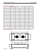


Model 4555 PanelIR
TM
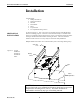
User Manual Installation
Multi-Zone Wiring
Prepare heater unit for wiring
Remove electrical connection
“knock-outs”
The Model 4555 can also be wired so that multiple heating zones are produced within
the heater. When configured for multi-zone operation, each zone of lamps is
electrically controlled by its own power control device. Wiring the Model 4555 for
multi-zone operation is as follows:
1. Remove the three screws from each of the end covers on each end of the heater
using the Phillips screwdriver.
2. Carefully remove each of the end covers and set them aside so that they are not
damaged.
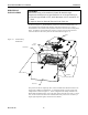
1. Three knock-outs are provided on each end of the Model 4555. Multiple knock-
outs can be removed on each end of the heater so that an individual knock-out does
not have to accommodate more than three or four wires. It is left up to the installer
to determine the number of knock-outs to remove to simplify the wiring procedure.
2. Using the hammer and punch, remove one circular “knock-out” from each end of
the top of the heater by placing the metal punch on the knock-out outline and
striking the punch with the hammer until the knock-out protrudes into the heater.
3. Using the pliers, remove the knock-out slugs from the heater body.
4. Discard the knock-out slugs.
1. Using the slotted screwdriver, loosen the screws holding the bus bar in the terminal
blocks.
2. Lift the bus bar out of the terminal strip.
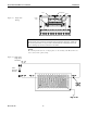
3. As shown in Figure 3-6, the bus and jumper bars can be cut to produce shorter,
individual jumpers corresponding to the number of desired heating zones. For
zones with more than 4 lamps, cut the bus bar the desired length. Use the jumper
bars for zones with 4 lamps or less. Move the plastic spacers so that they are
between the terminal blocks for each zone. They are required to insure electrical
isolation between zones.
4. Tighten each of the screws in the terminal blocks and jumper bars.
Research, Inc.
17