Model 4069P User’s Manual Publication #: 107663-001 Rev. _ Feb. 2009 Another quality product from: 7128 Shady Oak Road, Eden Prairie, MN 55344 Phone: (952) 949-9009 Fax: (952) 949-9559 E-mail: info@researchinc.com www.researchinc.
Model 4069P ProfileIRTM User Manual Section Contents page INTRODUCTION General Description Standard Features Optional Features 1 1 2 SAFETY General Gas Shock High Temperatures Electrical 3 3 3 3 SPECIFICATIONS Specifications Dimensions 4 6 INSTALLATION Wiring Control Connections Remote Interlock Switch Remote Fast Stop Water Connections Air Connections 8 10 10 10 10 10 OPERATION Main Disconnect Switch Operator Control Panel Panel View Terminal Main Screen Recipe Screen Alarms Screen Options Scre
Model 4069P ProfileIRTM User Manual Cleaning the Reflectors Removing the Reflectors Trouble-Shooting Spare Parts Contents 25 26 28 30
Model 4069P ProfileIRTM User Manual Introduction Introduction General Description The Model 4069P ProfileIR curing System uses high intensity infrared lamps and polished aluminum reflectors to deliver heat precisely where it is needed for many curing and drying applications on extrusion lines. It can be used effectively to provide a surface cure to rubber extrusions, dry adhesives and coatings on rubber or metal, and provide in process curing between layers of multi layer cable.
Model 4069P ProfileIRTM User Manual Standard Features Introduction Heater Positioning – The chamber is mounted to lifts at each end allowing for variations on product elevation. Each lift can operate independently allowing for up to 15° off chamber tilt. This can be useful when product sagging is occurring. Water Cooling – Each reflector is designed with an internal coolant passageway to allow coolant to flow through its entire length during operation.
Model 4069P ProfileIRTM User Manual Safety Safety General The Model 4069P heater is designed for safe operation. Nevertheless, installation, maintenance, and operation of the heater can be dangerous for a careless operator or maintenance person. For your safety and the safety of others, read the instructions in this instruction manual and follow these safety practices to help prevent accident or injury.
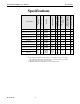
Model 4069 ProfileIRTM User Manual Specifications 4069P-12R-25L-30kW-480V 4069P-12R-38L-46kW-480V 4069P-12R-10L-DUAL18kW-480V 4069P-18R-10L-18kW-480V 4069P-18R-16L-29kW-480V 4069P-18R-25L-45kW-480V 4069P-18R-38L-68kW-480V 4069P-18R-10L-DUAL36kW-480V * 2500 3800 1000 1000 1600 2500 3800 1000 10 240 19.2 1.8 (6.9) 16 480 30.0 480 45.6 240 24 2.8 (10.6)** 4.2 (15.9)** 31 63 2.4 (9) 20 1.7 (6.5) 15 240 28.8 2.7 (10.2) 29 240 18.0 480 45.0 480 68.4 240 36 4.2 (15.7)** 3.1 (11.9)** 3.
Model 4069 ProfileIRTM User Manual Specifications 2 Inch Diameter ProfileIR Model 4069P Single Chamber 2 Inch Diameter Profile Model 4069P-12R-10L 4069-12R-16L 4069P-12R-25L 4069P-12R-38L Power Generated 12kW 19.2kW 30kW 45.
Model 4069 ProfileIRTM User Manual Specifications DIMENSIONS A 32.63 A INTERMEDIATE PRODUCT SUPPORT ROLLER Research, Inc. 6 6.
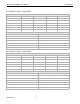
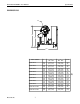
Model 4069 ProfileIRTM User Manual Specifications DIMENSIONS D DIA C B 44.00 MODEL NUMBER 4069P-12R-10L 4069P-12R-16L 4069P-12R-25L 4069P-12R-38L 4069P-18R-10L 4069P-18R-16L 4069P-18R-25L 4069P-18R-38L 4069P-12R-10L-DUAL 4069P-18R-10L-DUAL Research, Inc. 7 A 16.13 (410) 21.75 (552) 30.75 (781) 43.75 (1111) 16.13 (410) 21.75 (552) 30.75 (781) 43.75 (1111) 38.39 (975) 38.39 (975) B MIN MAX 36.75 44.75 (933) (1137) 36.75 44.75 (933) (1137) 36.75 44.75 (933) (1137) 36.75 44.75 (933) (1137) 38.00 46.
Model 4069 ProfileIRTM User Manual Installation Installation This section describes how to wire the Model 4069P power control system. The features and options mentioned here are identified in the model number found inside the enclosure. WIRING WARNING! Hazardous voltages are present at the main disconnect switch and load terminals. Always remove AC line voltage from the system before making contact with internal assemblies, line or load wiring, or fuses.
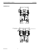
Model 4069 ProfileIRTM User Manual Installation CONNECT POWER THIS SIDE IF POSSIBLE Figure 1. Research, Inc.
Model 4069 ProfileIRTM User Manual Installation CONTROL CONNECTIONS Remote Interlock Switch This feature provides for remote process interlock of the heater power. This is accomplished by setting the heater power levels to 0 when switch is open and will resume power levels when switch is closed. With the interlock open, the heater cannot be turned on from the control system front panel. The switch contacts (dry) must be open during the heater off condition.
Model 4069 ProfileIRTM User Manual Figure 3 Operation Operation Main Disconnect Switch The main disconnect switch turns on and off the power control system. Note the following: Before turning on the disconnect switch, check the following: 1. The load is wired and ready for power to be applied to it. 2. Research, Inc. All safety precautions are observed.
Model 4069 ProfileIRTM User Manual Operation OPERATOR CONTROL PANEL The operator control panel consists of the PanelView terminal, right side and left side lift control switches, and a fast stop switch. Lift Control Switches (2) The white and black switches enable tilting of heater +/- 15° and have up/down travel of 8 inches. The white switch raises the heater, the black switch lowers the heater.
Model 4069 ProfileIRTM User Manual Operation PANELVIEW TERMINAL The PanelView terminal consists of a LCD display with keypad. 4 user screens are available: MAIN, RECIPE, ALARM, and OPTION. The selection of the screens are made with the F4 (NEXT SCREEN) key and the F5 (Previous Screen) key. The F5 key does not have a legend displayed on the screen. Note: The PanelView terminal is not a touchscreen, legends are displayed to guide the operator. All entries are made from the keypad. Research, Inc.
Model 4069 ProfileIRTM User Manual Operation MAIN SCREEN NOTE: The START key will not be displayed or active if the recipe displayed on the RECIPE screen and the loaded recipe, displayed on the MAIN screen do not match. Research, Inc. The MAIN screen allows monitoring of the system status, viewing the current recipe, Starting/Stopping the recipe and changing between Idle and Run.
Model 4069 ProfileIRTM User Manual Operation F3 IDLE key: This key will toggle the system between the zone power levels and the idle power levels. Zone power levels are displayed in the 6 pie shaped heater sections. The legend in the F3 box displays IDLE when running or RESUME while in IDLE. F4 NEXT SCRN key: This key will change the display to the next screen in the following order: MAIN, RECIPE, ALARMS, and OPTIONS. Each of these screens has the F4 key active.
Model 4069 ProfileIRTM User Manual Operation RECIPE SCREEN The RECIPE screen allows recipe selection, loading, creation or modification, and saving of up to twenty recipes. Recipe Selection The F1 key (RECIPE SELECT) will step through the recipes from 1 to 20 and wrap back to 1. The zone power levels and idle power level will be displayed as each recipe appears on the screen. The F5 key is does not have a legend displayed, but it will select the previous recipe.
Model 4069 ProfileIRTM User Manual Operation Recipe Creation/Modification After the recipe has been selected, changes can be made to it. The Tab (→| ) and Back Tab ( |← ) keys are used to move between the heating zones and idle power. The Enter key ( ↵ ) is used to open the data entry window to allow power level selection, 0 to 99%. The power level is entered on the numeric keypad keys 0-9. The escape key (ESC) will abort an entry that has been started.
Model 4069 ProfileIRTM User Manual ALARMS SCREEN Operation The ALARMS screen displays the status of each of the alarms. The dashed line (-----) indicates no alarm. Alarms are of one of two types, either a Critical or a Minor alarm. A Critical alarm will turn the system to off, dropping out the heater contactor. It is due to an abnormal condition that could damage equipment or harm personnel.
Model 4069 ProfileIRTM User Manual Operation REMOTE INTERLOCK The Remote Interlock alarm is a Minor alarm. This is a customer driven feature that can be used to signal a line stoppage or any occurrence where the heaters should be temporarily turned off. The opening of a dry contact is required to trip this alarm, a jumper is installed from the factory to bypass this alarm until it is hooked up. See the schematic for the location to make the connection. FAST STOP The Fast Stop Alarm is a Critical alarm.
Model 4069 ProfileIRTM User Manual OPTIONS SCREEN Operation The OPTIONS screen displays the status of each of the alarms. The dashed line (-----) indicates no alarm. Alarms are of one of two types, either a Critical or a Minor alarm. A Critical alarm will turn the system to off , dropping out the heater contactor. It is due to an abnormal condition that could damage equipment or harm personnel.
Model 4069 ProfileIRTM User Manual covered roller and sensor, when enabled it will change the output power level to 0 when no motion is detected for more than 2 seconds. Operation AIR CURE An optional air cure feature is available for the 4069P. The air cure feature, when installed, can be enabled and disabled by this selection. When enabled, a solenoid valve will be opened when starting a recipe, allowing compressed air, directed by adjustable nozzles, to be directed through the heating chamber.
Model 4069 ProfileIRTM User Manual Maintenance Maintenance and Trouble Shooting ROUTINE MAINTENANCE The following bi-monthly routine maintenance is suggested: 1. Remove power connection to the system. Lock out power if possible. Carefully vacuum any dust or dirt collecting within the enclosure. Use caution to not disturb the wiring. Service more often in dust locations. 2.
Model 4069 ProfileIRTM User Manual Maintenance Figure 6. 10. Cut wire to a length allowing for a service loop. 11. Strip back the insulation on the end of the lamp leads approximately 1-1/2 inches (38 mm). 12. Insert the bare wire of each insulated lamp lead into the ceramic terminal block position that previously held the old lamp. Push each lead wire into the terminal block far enough so, that when tightened, the setscrew will hold the lead securely. 13.
Model 4069 ProfileIRTM User Manual SPLIT QUARTZ LINER CLEANING AND REPLACEMENT Maintenance 1. 2. Open the Model 4069 Heater to allow access to each heater half for split quartz liner installation. Loosen the screws of one liner bracket and slide the bracket away from the quartz-liner of one liner half at one end of the heater, while supporting the liner with other hand. Figure 7 Figure 8 3. 4. Research, Inc. Remove the bracket from the end casting of the heater.
Model 4069 ProfileIRTM User Manual Maintenance Figure 9 5. 6. 7. 8. CLEANING THE REFLECTORS If cleaning the liner, use a non-abrasive glass cleaner (i.e. household ammonia and water or isopropyl alcohol) and a clean, dry, lint-free cloth. After cleaning, do not touch the outside surface of the liner unless wearing cotton gloves. Reinsert the edges of the liner into the grooves of the quartz-liner bracket. Reinstall the other bracket and secure with the two bracket screws.
Model 4069 ProfileIRTM User Manual REMOVING THE REFLECTORS Maintenance The reflectors can be removed from the Model 4069 Heater to make cleaning and maintenance easier. The following procedure should be used to remove the Model 4069 reflectors: Note: Remove all power from the heater BEFORE attempting to install/replace the heater reflectors. 1. Drain all cooling fluid from the heater and blow out the heater cooling lines with compressed air. 2. Remove the heater-cover screws and heater cover.
Model 4069 ProfileIRTM User Manual Maintenance Figure 11 3. 4. Disconnect the cooling line from the reflector to be maintained. Loosen all screw from all reflectors on one side of the end casting of the reflector to be maintained. 5. Remove the reflector mounting screws from the end casting of the reflector to be maintained. 6. Remove the reflector. Research, Inc.
Model 4069 ProfileIRTM User Manual TROUBLESHOOTING Maintenance Symptom System will not start. Action 1. Verify the F1 START legend is displayed on the MAIN screen. If not, the recipe on the MAIN screen and the recipe on the RECIPE screen do not match. Load the desired recipe with the F3 LOAD key on the RECIPE screen. 2. Check the STATUS box on the MAIN screen, if it is ALARM, go to the ALARM screen, find and clear the alarm. 3.
Model 4069 ProfileIRTM User Manual Maintenance PLC DIGITAL I/O MAPPING DIGITAL INPUTS DESCRIPTION 0 Flow Switch 1 Thermostat 2 Heater Closed 3 Fast Stop 4 5 Remote Interlock Motion Sensor DIGITAL OUTPUTS DESCRIPTION 0 Heater Enable 1 Cooling Solenoid / Fan 2 Heating Zone 1 3 Heating Zone 2 4 Heating Zone 3 5 Heating Zone 4 6 Heating Zone 5 7 Heating Zone 6 8 Air Cure Solenoid The PLC should have 3 green LED’s on: Power, Run, and the COM 0 LED should be flashing.
Model 4069 ProfileIRTM User Manual Maintenance Accessories, Spare, and Replacement Parts – Controls & Cart Model Description Control Cabinet: 096191-006 107556-009 086445-016 099395-001 099396-001 107549-001 080821-001 055899-015 066798-004 Contactor- 3 phase, 100 amp, 24 VDC coil Fuse-Cubefuse, 100 amp Fuse-Time Delay, “CC”, 6 amp, 600 VAC Switch-On /Off, 3 phase, 100 amp Switch Actuator-Red/Yellow Power Supply-480 VAC in, 24VDC out Relay-DPDT, 10 amp, 24VDC, 650 ohm Relay-SS, DC, 125 amp, 480 VAC Var
Model 4069 ProfileIRTM User Manual Maintenance Accessories, Spare, and Replacement Parts – Heater Model Description Replacement Lamp For: 103390-003 103390-004 103390-005 103390-007 103390-010 12kW or 18kW maximum-power rated heater (10 inch length, 1000-watts) 24kW or 36kW maximum-power rated heater (10 inch length, 2000-watts) 19kW or 29kW maximum-power rated heater (16 inch length, 1600-watts) 30kW or 45kW maximum-power rated heater (25 inch length, 2500-watts) 46kW or 68kW maximum-power rated heate