
Manual
Model 4069 ProfileIR
TM
User Manual Installation
Research, Inc. 8
WIRING
Installation
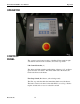
This section describes how to wire the Model 4069P power control system. The
features and options mentioned here are identified in the model number found inside
the enclosure.
WARNING!
Hazardous voltages are present at the main disconnect switch and load terminals.
Always remove AC line voltage from the system before making contact with internal
assemblies, line or load wiring, or fuses. Also remove AC line voltage from the
system
before making connections, equipment changes, or resistance measurements.
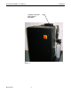
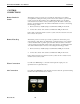
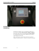
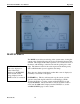
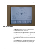
Conduit entry into the system should be made near the right side of the cabinet for
power wiring. Assure that metal fragments are not allowed to fall into the equipment
while holes are made for conduit fittings. See Figure 1. Referring to the wiring
specification in the table, connect the external power lines to the top of the disconnect
switch.
Wire Ratings:
Wire Temperature Rating:
75°C or Higher
Line/Load Wiring Voltage Rating (240 VAC systems) 300 VAC Minimum
Line/Load Wiring Voltage Rating (480 VAC systems) 600 VAC Minimum
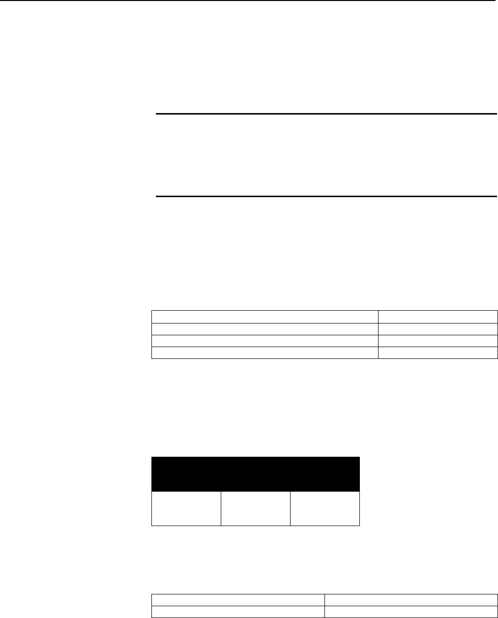
Minimum Allowable Wire Sizes:
NOTE:
Ampacity ratings are based on NEC 310-16 using 75
°
C copper wire.
Current
Rating of
System
Line
Connections
Ground
Connection
30 Amp
60 Amp
90 Amp
10 AWG
6 AWG
3 AWG
10 AWG
8 AWG
8 AWG
Remote Inputs:
Remote Interlock Dry contact (open to stop)
Fast Stop Dry contact (open to stop)