
Manual

Model 4069 ProfileIR
TM
User Manual Installation
Research, Inc. 10
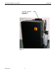
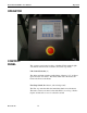
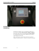
CONTROL
CONNECTIONS
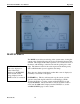
Remote Interlock
Switch
Remote Fast Stop
Water Connections
Air Connections
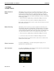
This feature provides for remote process interlock of the heater power. This is
accomplished by setting the heater power levels to 0 when switch is open and will
resume power levels when switch is closed. With the interlock open, the heater
cannot be turned on from the control system front panel. The switch contacts (dry)
must be open during the heater off condition. If this feature is desired, connect using
the following procedure:
1. Remove the factory-installed jumper at terminal block 1TB pins 20 and 21.
2. Connect the contacts of the switch to terminal block 1TB pins 20 and 21.
If more than one interlock switch is used in a system, wire the contacts in series and
then connect to the system.
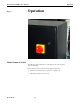
This feature provides for remote process fast stop shutdown of the heater power,
water and fan cooling. This is accomplished by opening the heater power controller
contactor. With the fast stop switch open, the heater cannot be turned on from the
control system front panel. The switch contacts (dry) must be open during the heater
off condition. If this feature is desired, connect using the following procedure:
3. Remove the factory-installed jumper at terminal block 1TB pins 22 and 23.
4. Connect the contacts of the switch to terminal block 1TB pins 22 and 23.
If more than remote fast stop switch is used in a system, wire the contacts in series
and then connect to the system.
Use male 3/8” NPT fittings to connect the water input and output ports. See
Specifications for required flow rates.
Use a male 3/8” NPT fitting for the air input connection when the optional Air Curing
Nozzles and/or Pyrometer have been ordered.