
Manual

Model 4069 ProfileIR
TM
User Manual Maintenance
Research, Inc. 29
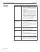
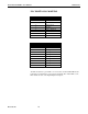
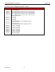
PLC DIGITAL I/O MAPPING
DIGITAL INPUTS
DESCRIPTION
0 Flow Switch
1 Thermostat
2 Heater Closed
3 Fast Stop
4 Remote Interlock
5 Motion Sensor
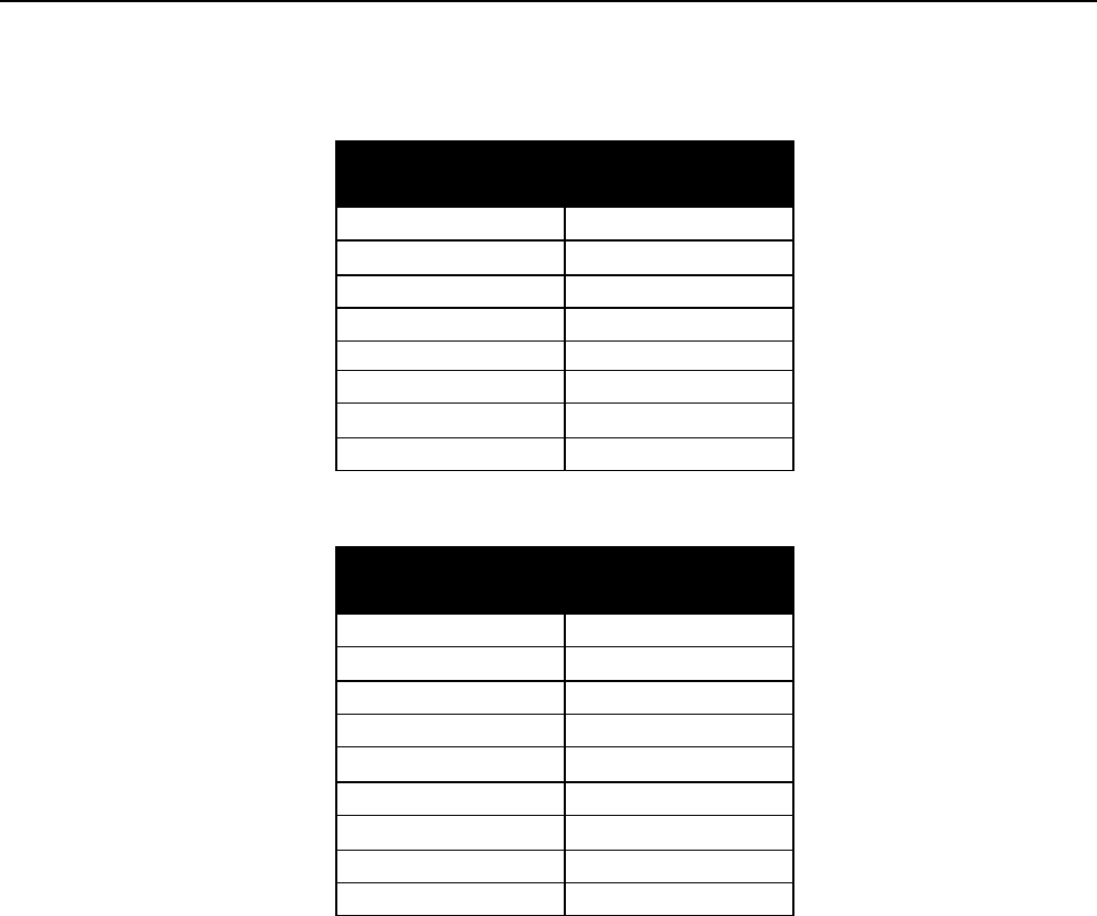
DIGITAL OUTPUTS
DESCRIPTION
0 Heater Enable
1 Cooling Solenoid / Fan
2 Heating Zone 1
3 Heating Zone 2
4 Heating Zone 3
5 Heating Zone 4
6 Heating Zone 5
7 Heating Zone 6
8 Air Cure Solenoid
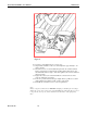
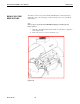
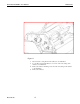
The PLC should have 3 green LED’s on: Power, Run, and the COM 0 LED should
be flashing. (Communications to the Operator Terminal) The Amber LED’s on the
PLC indicate the state of the Digital Inputs and Outputs.