AMPLIFIER MODELS A500/2 A800/2 A1000/2
TABLE OF CONTENTS Congratulations . . . . . . . . . . . . . . . . . . . . . . . . . . . . . . . . . . . . . . .2 Service . . . . . . . . . . . . . . . . . . . . . . . . . . . . . . . . . . . . . . . . . . . . . .2 Caution . . . . . . . . . . . . . . . . . . . . . . . . . . . . . . . . . . . . . . . . . . . . .2 Features . . . . . . . . . . . . . . . . . . . . . . . . . . . . . . . . . . . . . . . . . . . . .2 What’s Included . . . . . . . . . . . . . . . . . . . . . . . . . . . . . . . . . . . . . . .
CONGRATULATIONS Thank you for choosing Precision PowerTM audio equipment. Designed and engineered in the USA, this product combines innovative technology with the finest materials to consistently deliver Absolutely State of the Art™ performance, sound quality, reliability, and value. This Precision PowerTM product reflects our commitment to offer you unparalleled performance and quality for years of dependable service and listening enjoyment.
High Voltage Input Capability with -12dB Attenuation Switch. Gold Plated RCA Input and Output Connectors. PowerLockTM Speaker and Power Wire Connectors. WHAT’S INCLUDED Amplifier (with speaker and power plugs mounted) (4) Mounting screws and washers 2mm hex wrench 2.5mm hex wrench 3mm hex wrench CEA SPECIFICATIONS A500/2 Power Output: 80 Watts RMS x 2 at 4 ohms and < 1% THD+N Signal to Noise Ratio: -70 dBA (reference 1 Watt into 4 ohms) Additional Power Output: 125 Watts RMS x 2 at 2 ohm at 14.
SPECIFICATIONS Nominal Power Ratings MODEL A500/2 A800/2 A1000/2 4 2 2 2 ohm X 75 X 125 X 175 2 2 2 2 ohm X 125 X 200 X 250 4 1 1 1 ohm MONO X 250 X 400 X 500 General Specifications Load Impedance (Stereo) Load Impedance (Bridged) Input Topology Conversion Efficiency Frequency Response Linear Bandwidth Input Sensitivity RCA Output Jacks Input Impedance Supply Voltage Damping Factor 2–8 ohms 4–8 ohms Balanced differential >50% @2 ohms max power 20Hz–200Hz ±0.
Fuse Requirements You will need to install an in-line fuse or circuit breaker in the power wire within 18” of the battery. This fuse or circuit breaker is to protect your vehicle from fire in case the power wire shorts to the vehicle body. If you are only using one amplifier, use the fuse rating indicated in this chart. If you are using more than one amplifier, add up the fuse ratings for all the amplifiers. This sum is the rating for your fuse or circuit breaker.
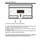
AMPLIFIER STATUS LEDS 1 2 The LEDs provide the following indications: 1. Power - These LEDs illuminates the center Precision Power logo background when the amplifier power is turned on. 2. Short - These LEDs behind the PPI logo will flash to indicate a short on the output. 2. Thermal - These LEDs behind the PPI logo will extinguish if the amplifier is in thermal shutdown protection. Note: Read the AP-IV Protection Circuit section for additional information regarding Short and Thermal protection.
TOOLS/PARTS FOR INSTALLATION NOTE: TOOLS ARE NOT SUPPLIED. Small flat blade screwdriver Phillips screwdriver (#2 or medium sized) Wire cutters Wire strippers 4 - #6 round head screws, and 1 - #8 sheet metal screw.
Note: The cables running from the battery to the rear of the car should be installed on the side of the car opposite to the antenna. When using 16 gauge wire or larger, run the speaker wires from the amplifier location through the vehicle to the speakers. Observe the same precautions for routing these wires that you followed for running the power and remote turn on wires. Cut off excess and, using wire strippers, strip 1/4-inch of insulation. Locate the speaker/remote turnon PowerLockTM connector.
Note: The amplifier comes with the connector inserted into the amplifier with the wire clamping screws in the up position as shown below. Use a 2mm hex head wrench to secure the wires to the connector. If the connector needs to be unplugged from the amplifier, use a 2.5mm hex head wrench to remove the retaining screw from the connector (set aside and save the retaining screw). The two negative outputs are common to each other as are the two positive outputs. A speaker may be connected to either terminal.
wires as close together as possible, and use the same gauge wire for both. This will ensure that you have a good ground path, and may eliminate such potential problems as engine noise and overheated amplifiers. CHARGING SYSTEM If your total current draw is over 100 amps (or total output power is over 600 watts), you are probably exceeding the capability of your charging system. Dimming lights and fluctuating voltage are solid indicators that you need to upgrade your alternator, battery, or both.
375W = 31.25 Amps total current draw 12V If the same amplifier is driven into a 2 ohm stereo or 4 ohm mono load, double it’s 4 ohm RMS rating. These amplifiers will effectively double their power at this load. 250W X 1.5 X2 = 750 watts 750W = 62.5 Amps total current draw 12V If you are using more than one amplifier, add up the total current draw for all of them and choose the appropriate gauge based on the grand total.
POWERLOCK CONNECTORS Once you have run both the power and ground wires, then connect the cables to the amplifier. Cut off excess wire, and using wire strippers, strip the ends of the power and ground cables approximately 1/4 inch. Locate the PowerLockTM power and ground connector (supplied). Using a hex wrench, loosen the screws before attempting to insert the cable wires. Insert the wires into the appropriate hole, and tighten the screws.
FRONT PLATE DIAGRAM 12 11 R R- R BRIDGE + R+ REM L+ L- OUTPUT XOVER FREQ QBASS ATT XOVER GAIN LP L 30 LP 40k OUTPUT FREQ FULL HP 1 2 3 4 2 5 1 -12dB 6 MIN MAX 30 L 40k INTPUT FREQ FULL HP 7 8 9 10 1. Cooling Plenums: Maintain a minimum 2” clearance around cooling plenums for proper amplifier cooling. 2. Speaker/Remote Connector: The PowerLockTM speaker connector. 3. Output Xover Freq.
QBass frequency control adjustment. 12. RCA Outputs: RCA outputs provide HP/LP/FULL 30-4kHz signal to another amplifier. END PLATE DIAGRAM +18 0 QBASS REMOTE QBASS 1 2 3 4 1. Cooling Plenums: Maintain a minimum 2” clearance around cooling plenums for proper amplifier cooling. 2. Power/Ground PowerLockTM: Connect your power and ground to this Power/Ground PowerLockTM connector. Note: Item descriptions 3 and 4 only apply to the A800/2 and A100/2 amplifiers. 3.
INPUTS There are two sets of RCA jacks on the front end of your amplifier. The RCA cables from your source unit go in the set labeled INPUTS. If your source unit doesn’t have RCA outputs, then add a set of RCA plugs (available at your dealer) to your front or rear set of speaker leads (see drawing below). Plug them into the input jacks, and push in the -12dB input attenuation switch.
QBASS PLUS SPECIFICATIONS Note: Not available on the model A500/2 amplifier. QBASS PLUSTM Up to 18dB of boost with selectable center frequency at 30Hz, 36Hz, 44Hz or 60Hz, with a Q-factor of 2. Optional QBASS REMOTETM This boost control can be mounted in the dash and will supersede the boost control on the amplifier endplate.
QBASS PLUS/QBASS REMOTE On A800/2, and A1000/2 amplifiers, we’ve taken bass control to a higher level with QBASS PLUSTM. The two QBASSTM switches (labeled 1 and 2) on the front end of the amplifier allow you to select one of four frequency centers 30Hz, 36Hz, 44Hz and 60Hz. On the rear end plate you will find the QBASSTM level control and plug-in for an optional QBASS REMOTETM dash mounted level control. Adjust the level control clockwise for up to +18dB of boost at your selected frequency.
TC-X CROSSOVER Your new amplifier has a TC-X Crossover (Total Control X-over®) 30Hz-4kHz (see this guide for Crossover Chart).12dB per octave phase correlated crossover built-in to provide superior system flexibility without the added expense and installation of an outboard crossover. The speaker outputs of your amplifier are high pass, low pass, or all-pass according to the HP/LP/FULL switch on the front endplate.
CROSSOVER DETENT CHART Detent # 1 2 3 4 5 6 7 8 9 10 11 12 13 14 15 16 17 18 19 20 21 22 23 24 25 26 27 28 29 30 31 32 33 34 35 36 37 38 39 40 41 Low Pass Frequency (Hz) @ -3dB 28 28 30 30 30 32 34 36 38 42 46 50 52 54 60 66 76 88 100 116 136 144 168 198 240 286 310 340 380 424 484 576 632 748 932 1076 1428 1700 2436 2830 2980 19 High Pass Frequency (Hz) @ -3dB 52 52 52 56 56 60 64 72 76 80 88 92 100 116 132 148 168 192 216 244 284 348 404 468 512 564 624 700 800 932 1036 1144 1300 1504 1812 2196 2840 41
ADJUSTING INPUT GAIN 1. Adjust all amplifier input gain controls to just above minimum sensitivity (fully counterclockwise). 2. Using the cleanest music source (CD) playing, turn up the head unit source volume until you can hear distortion. Now turn it down a bit until you cannot hear the distortion (usually just below full volume). 3. Increase the amplifier gain (clockwise) until the onset of audible distortion. Then decrease the gain to the point just before the distortion starts.
TROUBLESHOOTING NO SOUND Is the LED illuminated? YES NO Check Power and Remote turn-on wire for voltage. Make sure the ground wire is secure. STILL NO SOUND See your Authorized Precision PowerTM Dealer or call 1-800-62POWER. SOUND IN ONE CHANNEL ONLY Reverse the left and right speakers by unplugging the speaker connector, turning it over and plugging it back in. SOUND IS NOW IN OPPOSITE CHANNEL SAME CHANNEL Reverse RCA inputs. Problem is in the speaker or speaker wire of the silent channel.
LIMITED TWO YEAR CONSUMER WARRANTY: Directed Electronics promises to the original purchaser, to replace this product should it prove to be defective in workmanship or material under normal use, for a period of two years from the date of purchase by the dealer as indicated by the date code marking of the product PROVIDED the product was installed by an authorized Directed dealer.