TABLE OF CONTENTS Congratulations . . . . . . . . . . . . . . . . . . . . . . . . . . . . . . . . . . . . . . .2 Service . . . . . . . . . . . . . . . . . . . . . . . . . . . . . . . . . . . . . . . . . . . . . .2 Caution . . . . . . . . . . . . . . . . . . . . . . . . . . . . . . . . . . . . . . . . . . . . .2 Features . . . . . . . . . . . . . . . . . . . . . . . . . . . . . . . . . . . . . . . . . . . . .3 QBASS PLUS Specifications . . . . . . . . . . . . . . . . . . . . . . . . . . . .
CONGRATULATIONS Thank you for choosing PrecisionPowerTM audio equipment. Designed and engineered in the USA, this product combines innovative technology with the finest materials to consistently deliver Absolutely State of the Art™ performance, sound quality, reliability, and value. This PrecisionPowerTM product reflects our commitment to offer you unparalleled performance and quality for years of dependable service and listening enjoyment.
FEATURES New! Advanced Instrumentation Input Stage. New! 24dB/Octave; HP/LP/FULL; 30-4kHz Crossover. New! Independent Line Output Crossover 30-4kHz PWM Power Supply Triple Darlington Output Stage. AP-IV Protection Circuity QBASSTM Bass Boost High Voltage Input Capability with -12dB Attention Switch. Gold Plated RCA Input and Output Connectors. PowerLockTM Speaker and Power Wire Connectors. 2 Yr Warranty; if installed by an Authorized PrecisionPower Dealer.
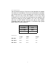
SPECIFICATIONS Power Ratings MODEL DCX 500.1 DCX 1000.1 DCX 1500.1 4ohm MONO 1 X 200 1 X 400 1 X 500 2ohm MONO 1 X 300 1 X 600 1 X 1000 1ohm MONO 1 X 500 1 X 1000 1 X 1500 All power ratings given above are tested at 12.5V; 4 ohms; 20Hz - 200Hz.
Fuse Requirements You will need to install an in-line fuse or circuit breaker in the power wire within 18” of the battery. This fuse or circuit breaker is to protect your vehicle from fire in case the power wire shorts to the vehicle body. If you are only using one amplifier, use the fuse rating indicated in this chart. If you are using more than one amplifier, add up the fuse ratings for all the amplifiers. This sum is the rating for your fuse or circuit breaker.
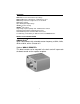
AMPLIFIER STATUS LEDS 3 SHORT PROTECT POWER 4 THERMAL PROTECT CLIP OUT 1 2 The LEDs provide the following indications: 1. Power - This LED illuminates RED when the amplifier power is turned on with the remote input (output muted). After a short time delay this LED will turn GREEN (amplifier ready). 2. Clip Output - This LED illuminates RED on the peaks of the output signal when the peaks are too high. This clipping causes audible distortion in the speakers. 3.
TOOLS/PARTS FOR INSTALLATION NOTE: TOOLS ARE NOT SUPPLIED. Small flat blade screwdriver Phillips screwdriver (#2 or medium sized) Wire cutters Wire strippers 4 - #6 round head screws, and 1 - #8 sheet metal screw.
Note: The cables running from the battery to the rear of the car should be installed on the side of the car opposite to the antenna. When using 16 gauge wire or larger, run the speaker wires from the amplifier location through the vehicle to the speakers. Observe the same precautions for routing these wires that you followed for running the power and remote turn on wires. Cut off excess and, using wire strippers, strip 1/4-inch of insulation. Locate the speaker/remote turnon PowerLockTM connector.
Note: The power connector is inserted into the amplifier with the wire clamping screws in the up position as shown below. The two negative outputs are common to each other as the two positive outputs. A speaker may be connected to either terminal. GROUND WIRING Locate an area near the amplifier(s) that is metal and clean an area about the size of a quarter down to bare metal. Inspect the area around and underneath to be sure you will not drill into wires, brake or fuel lines, etc.
over 600 watts), you are probably exceeding the capability of your charging system. Dimming lights and fluctuating voltage are solid indicators that you need to upgrade your alternator, battery, or both. You should also check the condition and current capacity of the stock battery negative cable and connections, and replace or upgrade as necessary.
If the same amplifier is driven into a 2 ohm stereo or 4 ohm mono load, double it’s 4 ohm RMS rating. All DCX amplifiers will effectively double their power at this load. 500W X 1.5 X2 = 1500 watts 1500W = 125 Amps total current draw 12V If you are using more than one amplifier, add up the total current draw for all of them and choose the appropriate gauge based on the grand total. POWER WIRE SIZE A minimum of 8 gauge or a maximum of 4 gauge wire is recommended dependent on the application.
POWERLOCK CONNECTORS Once you have run both the power and ground wires, then connect the cables to the amplifier. Cut off excess wire, and using wire strippers, strip the ends of the power and ground cables approximately 1/4 inch. Locate the PowerLockTM power and ground connector (supplied). With a small flat blade screwdriver, loosen the screws before attempting to insert the cable wires. Insert the wires into the appropriate hole, and tighten the screws.
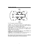
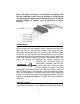
DCX-500.1, 1000.1, 1500.1 FRONT PLATE DIAGRAMS 14 13 12 11 10 DCX500.1, 1000.1, 1500.1 Front Panel R OUTPUT XOVER PHASE ATT 0° -12dB 180° 1 2 LPF QBASS QBASS 5 6 R XOVER LP REM 1 2 30 L OUTPUT 4k 30 FREQ FULL HP 3 4 250 7 20 MIN MAX L INPUT GAIN FULL HP 8 100 HPF 9 1. Cooling Plenums: Maintain a minimum 2” clearance around cooling plenums for proper amplifier cooling. 2. Speaker/Remote Connector: Plug in the PowerLockTM connector here. 3. Output Freq.
12. -12dB Input Attenuation: Push this switch ‘IN’ for high voltage (4V-12V) capability. This button pushed ‘IN’ must be used for speaker level input on common ground head-units or for high voltage line drivers. 13. Phase: Adjust the phase of the output relative to the amplifier input. 14. RCA Outputs: RCA outputs provide HP/LP/FULL 30-4kHz signal to another amplifier. DCX-500.1, 1000.1, 1500.1 END PLATE DIAGRAMS 1 2 3 4 DCX500.1 Rear Panel QBASS QBASS REMOTE 0 1 1 2 +16 4 3 DCX1000.1, 1500.
3. QBASSTM Level Control: Controls bass boost, centered at 40Hz with up to 18dB of boost. 4. Cooling Plenums: Maintain a minimum 2” clearance around cooling plenums for proper amplifier cooling. INPUTS There are two sets of RCA jacks on the front end of your amplifier. The RCA cables from your source unit go in the set labeled INPUTS. If your source unit doesn’t have RCA outputs, then add a set of RCA plugs (available at your dealer) to your front or rear set of speaker leads (see drawing below).
ADVANCED INSTRUMENTATION INPUT The Advanced Instrumentation Input has been incorporated from the legendary PrecisionPowerTM 2500F1. This circuit completely isolates the chassis ground from the audio circuit of the amplifier and reduces noise radiated into your signal cables by up to 40dB. This is equivalent to a noise reduction of approximately one hundred times what the noise level would be without this circuitry.
QBASS PLUS/QBASS REMOTE On DCX 500.1, DCX 1000.1, and DCX 1500.1 amplifiers, we’ve taken bass control to a higher level with QBASS PLUSTM. The two QBASSTM switches (labeled 1 and 2) on the front end of the amplifier allow you to select one of four frequency centers 30Hz, 36Hz, 44Hz and 60Hz. On the rear end plate you will find the QBASSTM level control and plug-in for an optional QBASS REMOTETM dash mounted level control.
TC-X CROSSOVER Your new DCX amplifier has a TC-X Crossover (Total Control Xover®) 30Hz-4kHz (see this guide for Crossover Chart).12dB per octave phase correlated crossover built-in to provide superior system flexibility without the added expense and installation of an outboard crossover. The speaker outputs of your amplifier are high pass, low pass, or all-pass according to the HP/LP/FULL switch on the front endplate.
CROSSOVER DETENT CHART Detent # 1 2 3 4 5 6 7 8 9 10 11 12 13 14 15 16 17 18 19 20 21 22 23 24 25 26 27 28 29 30 31 32 33 34 35 36 37 38 39 40 41 Low Pass Frequency (Hz) @ -3dB 28 28 30 30 30 32 34 36 38 42 46 50 52 54 60 66 76 88 100 116 136 144 168 198 240 286 310 340 380 424 484 576 632 748 932 1076 1428 1700 2436 2830 2980 19 High Pass Frequency (Hz) @ -3dB 52 52 52 56 56 60 64 72 76 80 88 92 100 116 132 148 168 192 216 244 284 348 404 468 512 564 624 700 800 932 1036 1144 1300 1504 1812 2196 2840 41
ADJUSTING INPUT GAIN 1. Adjust all amplifier input gain controls to just above minimum sensitivity (fully counterclockwise). 2. Using the cleanest music source (CD) playing, turn up the head unit source volume until you can hear distortion. Now turn it down a bit until you cannot hear the distortion (usually just below full volume). 3. Increase the amplifier gain (clockwise) until the onset of audible distortion. Then decrease the gain to the point just before the distortion starts.
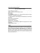
NO SOUND Is the LED illuminated? YES NO Check Power and Remote turn-on wire for voltage. Make sure the ground wire is secure. STILL NO SOUND See your Authorized PrecisionPowerTM Dealer or call 1-800-62POWER. SOUND IN ONE CHANNEL ONLY Reverse the left and right speakers by unplugging the speaker connector, turning it over and plugging it back in. SOUND IS NOW IN OPPOSITE CHANNEL SAME CHANNEL Reverse RCA inputs. Problem is in the speaker or speaker wire of the silent channel.