TM PAR 245 5 Band Equalizer / Preamp OWNERS MANUAL POWER CLASS CONTENTS (click on a topic to view) Congratulations System Tuning Features and Specifications System Tuning Mounting Frequency Distribution Mounting Frequency / Q Selection Code Wiring Frequency / Q Selection Code Wiring System One Functions System Two Functions System Three System Tuning Troubleshooting System Tuning Block Diagram System Tuning Warranty
Congratulations and thank you..... for choosing PrecisionPower audio epuipment. At PrecisionPower we proudly design, engineer and manufacture audio products at our facility in Phoenix, Arizona. Our award winning engineering team utilizes innovative technology to consistently deliver Absolutely State of the Art performance, sound quality, reliability, and value.
FEATURES / SPECIFICATIONS 5 Band Parametric Equalizer Preamp Line Driver Choice of 16 Selectable Frequency/Q Settings for Each Band Front and Rear Outputs with Fader Control Dual Selectable Illumination Center-Detented Boost/Cut Controls ±15 dB Boost/Cut for Each Band Defeat Switch Gold-plated RCA Input and Output Connectors PWM (Pulse Width Modulated) Power Supply Independent L & R Input Gain Adjustments Input Clip Indicator Designed and Handcrafted in the U.S.A.
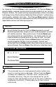
MOUNTING Mounting To prevent damage to the PAR-245 while driving, mount it in a secure place. Choosing the appropriate location will depend upon your vehicle and the complexity of your system design. Typical mounting locations for your new PAR-245 would be in the dash or center console. Never mount the component in a location that would subject it to immersion or exposure to water. Once a location has been chosen, securely mount the PAR-245 using the two supplied brackets.
MOUNTING R L R L R L In-C lip Dimensions 6.75"W 4.60" L 0.
WIRING eject 2 1 5 BASS 6 7 4 Trk 1 8 PPI TRACK RIGHT LEFT F 3 TREBLE BALANCE VOLUME Volume FOWARD MAR KET ING DPT REVERSE + R + + + + Power In-Clip Fader Defeat Sub Low Low-Mid High-Mid Treble PAR-245 NOTE Before beginning, disconnect the negative (-) terminal of the battery prior to working on the positive (+) terminal to prevent a short to ground. This is important, unless you want to spend the rest of your life with a nickname like "Sparky," or "Smokey.
WIRING The next step is to connect the Power, Ground, and Remote wires to your PAR-245. The power wire should run from the mounting location through the vehicle to the battery or power distribution block. Avoid sharp corners, creases, and sharp body parts. When passing through any metal wall (i.e. firewall etc.), a grommet must be used to prevent the wire from chaffing and shorting to ground. The ground wire should be of the same gauge as the power wire.
FUNCTIONS 1. Input Gold plated RCA inputs. Plug in the RCA cables from the source unit here. 2. Rear Output Gold plated RCA outputs. Plug in the RCA cables to your rear channel amplifier here. 3. Front Output Gold plated RCA outputs. Plug in the RCA cables to your front channel amplifier here. 4. LED Select Push this switch IN for Red Illumination, Leave it OUT for Green. 5. Power After connecting the Power, Ground and Remote wires, plug in the PowerLock connector here. 6, 7.
FUNCTIONS 1 2 3 4 5 + + + + + 6 7 8 9 10 1. Power LED Red light indicates power on. 2. Input Clip Input-Clip indicator lights when the PAR-245 is overdriven. With the source unit at 3/4 full volume, adjust the input sensitivity so that the light blinks only on very loud material. 3. Volume Leave the source unit at 3/4 full volume, and use this control as the Master volume control. 4. Fader Controls the output level to Front and Rear. 5.
SYSTEM TUNING System Gain Adjustment In order to achieve maximum signal-to-noise performance from a high quality auto stereo system, it is desirable to use high signal levels wherever possible in the interconnect cables. High signal levels will reduce the effect of induced noise. The peak level of an audio signal is usually determined by the clipping level of electronic components. The following procedure should be used as a guide before the system installation is completed.
SYSTEM TUNING Parametric Operation The PAR-245 Equalizer/Preamp puts an incredible amount of control at your fingertips. Correctly adjusted, it can solve many of the problems you will encounter along your road to perfect sound. By following these guidelines, you will avoid common pitfalls in system tuning and get your sound quickly dialed in. We recommend that you use a Real Time Analyzer (RTA) to speed things up, but it is possible to tune your system without it.
SYSTEM TUNING NOTE: If you are using the PAR-245 as well as another equalizer (like the DEQ-230 or PMQ-210) Go to step 11. 1) The first step is to locate a suitable source of “pink noise." A good choice would be the current IASCA competition reference disc. Also, some RTAs have a built-in pink noise source. Ideally, the pink noise should play through your head unit, allowing you to compensate for any frequency response changes caused by it, or anything else, before the amplifiers.
SYSTEM TUNING 4) If electronic crossovers are used, any large frequency sections corresponding to your crossover points that are low or high should be brought in line using crossover level controls or amp gain adjustments rather than the equalizer. 5) To begin, you will probably see several peaks and dips in your RTA curve. Find the lowest offending frequency, and choose the appropriate frequency range control on the top of the PAR-245.
SYSTEM TUNING 8) Move to the next peak or dip, and repeat the process until you run out of frequencies to adjust. Try to remove the peaks before filling the dips. Periodically, while you are making adjustments, compare the new curve you are making to the system in an unequalized state by using the defeat switch on the front face plate of the PAR-245. PPI THIRD OCTAVE REAL TIME SPECTRUM ANALYZER RTA 12 09 06 03 00 03 06 09 12 25 31.5 40 50 63 80 100 125 160 200 250 315 400 500 630 800 1K 1.25K 1.
FREQUENCY DISTRIBUTION FUNDAMENTAL NOTE HARMONIC OR OVERTONE 25 50 100 200 400 800 1.6 3.2 6.4 12.
FREQUENCY/Q SELECTION CODES 14 BACK TO CONTENTS
FREQUENCY/Q SELECTION CODES PAR-245 Frequency Controls Use a small flat-bladed screwdriver to change the Frequency/Q selection switches to the settings following the System Tuning guidelines.
SYSTEM ONE Source Unit eject BASS 1 2 5 6 3 4 7 8 Trk 1 TREBLE BALANCE VOLUME FOWARD MAR PPI TRACK RIGHT LEFT KET ING DPT REVERSE Input L R R OutpRear ut L t pu In ty vi ti nsi Se Front Outp ut L R Precis PAR245ionPower Vol ume Powe r 1 2 3 4 Sub Low-M F In-Cl id High-Mid R ip + Fade r at ct Power Treble Made in USA + Defe LED Sele Frequenc y Adju st Low + Sub + Low + Low -Mid High -Mid Treb PAR- 245 14K Hz -23.
SYSTEM TWO Source Unit eject BASS 1 2 5 6 3 4 7 8 Trk 1 TREBLE BALANCE VOLUME PPI TRACK RIGHT LEFT FOWARD MAR KET ING DPT REVERSE Input L R R OutpRear ut L t pu In ty vi ti nsi Se Front Outp ut L R Precis PAR245ionPower Vol ume Powe r 2 3 4 Sub 1 High-Mid R + Fade r Power Treble Made in USA + Defe at ct Low-M id ip LED Sele Frequenc y Adju st Low F In-Cl + Sub + Low + Low -Mid High -Mid Treb le PAR- 245 PAR-245 Preamp/Equalizer Front Output R
SYSTEM THREE Source Unit eject 3 4 7 8 Trk 1 MAR PPI KET ING DPT REVERSE Made zer e Equali Octav in USA KH z 6.4 -12db 20 +12d b 10 -12db KH z -12db +12d b +12d b KH z 1.6 -12db 4 KH z +12d b +12d b Hz -12db 5 KH z +12d b -12db 800 -12db 2 KH z +12d b Hz 400 +12d b -12db +12d b 2.5 +12d b -12db KH z -12db 1 KH z +12d b Hz 200 -12db Hz +12d b 1.
TROUBLE SHOOTING NO SOUND Is the LED lit? YES Check Input cables for signal by connecting them to the next component in line. NO Check Power and Remote turn-on wire for voltage. Make sure Ground wire is secure. ANY SOUND NOW? YES NO Problem is in the Equalizer. See your Problem is elsewhere in the system. local Authorized PrecisionPower Dealer Check head unit and amplifiers. or call1-800-62POWER. SOUND IN ONE CHANNEL ONLY Check Balance control. Reverse left and right RCA outputs.
BLOCK DIAGRAM 20 BACK TO CONTENTS
WA R R A N T Y Three-Year Limited U.S.A. Warranty This warranty gives you specific legal rights, and you may also have other rights which vary from state to state. PrecisionPower warrants its products to be free from defects in materials and workmanship under normal use and service for a period of three (3) years from the date of original purchase when the unit is installed by an Authorized Dealer.