OWNERS MANUAL PC360.2 / PC650.2 PC400.4 / PC640.4 / PC1000.1 / PC740.
Table of Contents Congratulations 3 Features 4 Specifications 5-6 Installation 7 Controls and Terminals 8-9 Control Definitions 10-12 System Diagrams 13-21 Troubleshooting 22 <2>
CONGRATULATIONS Thank you for choosing Precision PowerTM audio equipment. Designed and engineered in the USA, this product combines innovative technology with the finest materials to consistently deliver Absolutely State of the Art™ performance, sound quality, reliability, and value. This Precision PowerTM product reflects our commitment to offer you unparalleled p erformance and quality for years of dependable service and listening enjoyment.
FEATURES • Sequenced Delays Eliminate Residual Power-Up/Power-Down Pops. • Differential RCA Inputs Isolate 12V/Audio to Ground, Eliminating Ground Loops and Noise. • Full Signal Path Low Noise/Distortion Circuitry Topology. • Optimal Component Layout for Minimal Distortion Induction & Signal Separation.
SPECIFICATIONS PC360.2 Channels PC650.2 PC400.4 PC640.4 2 2 4 4 RMS Power @ 4Ω, 14.4V 110W X 2 195W X 2 70W X 4 115W X 4 RMS Power @ 2Ω, 14.4V 180W X 2 325W X 2 100W X 4 160W X 4 RMS Power @ 4Ω Bridged 360W X 1 650W X 1 200W X 2 320W X 2 0.02% 0.02% 0.02% 0.
SPECIFICATIONS PC740.5 PC1000.1 5 1 RMS Power @ 4Ω, 14.4V Channels 70W X 4, 275W X 1 - RMS Power @ 2Ω, 14.4V 100W X 4, 450W X 1 1000W X 1 RMS Power @ 4Ω Bridged 200W X 2 - - 1000 x 1 RMS Power @ 1Ω, 14.4V 0.02% 0.02% Frequency Response Total Harmonic Distortion (4Ω power) 15-50KHz 15-200Hz Input Sensitivity 200mV-9V 200mV-9V Signal-to-Noise Ratio (4Ω power) 104dB 102dB Damping Factor (100Hz, 4Ω) >1400 >2400 2” X 10” X 16.75” 2.3” X 10” X 16.
Installation Before installing any audio equipment, it is good practice to disconnect the ground terminal on the battery to avoid damage to the vehicle or audio equipment. Failure to do this means you’re a few brews short of a 6-pack and you probably already acquired the nickname of “Sparky” or “Smokey”. Not cool! Do NOT hook the ground cable back up to the battery until the rest of the wiring is complete.
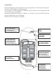
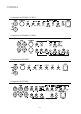
TERMINALS * Power terminal block & Speaker terminal block for PC360.2 / PC650.2 * Power terminal block & Speaker terminal block for PC400.4 / PC640.4 * Power terminal block & Speaker terminal block for PC1000.1 * Power terminal block & Speaker terminal block for PC740.
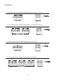
CONTROLS * Crossovers for PC360.2 / PC650.2 * Crossovers for PC400.4 / PC640.4 * Crossovers for PC1000.1 * Crossovers for PC740.
Control Definitions Alrighty, here comes the fun stuff. We’re going to break this down to it simplest form so that there is no way you can possibly do any damage in the installation process to your audio system. We’re going to explain in detail how every single knob and switch work rather than turn you loose on a sophisticated amplifier and have problems. READ EVERYTHING! Trust us, it’ll be worth it… Before you do anything, undo the ground cable from the battery.
Crossovers(continued..) Xover Mode Switch – Select HP/FR for High Pass / Full Range and only the HIGH PASS functions will work. The High Pass filter is ne ver off, but can be set to 15Hz which passes the entire audible spectrum to be reproduced. If you select LP/BP for Low Pass and Band Pass, then the LOW PASS function works as well. You can use the Low Pass in conjunction with the always-on High Pass to band pass the signal to the drivers. For example...
Crossovers(continued..) Remote Control – This the port for the Remote Control so you can use the supplied unit to control the gain from the front of the vehicle. Input Mode – When in 4CH mode, all 4 channels of signal are required and fadability is in effect. When in 2CH mode, only 2 channels of signal are required and CH1&3 get the same signal, and CH2&4 get the same signal. Fadability is lost in 2CH mode.
System Diagrams MONO Channel System Design #1 PC1000.
System Diagrams 2Channel System Design #1 PC360.2 / PC650.2 2Channel System Design #2 PC360.2 / PC650.
System Diagrams 2Channel System Design #3 PC360.2 / PC650.
System Diagrams 4Channel System Design #1 PC400.4 / PC640.
System Diagrams 4Channel System Design #2 PC400.4 / PC640.
System Diagrams 4Channel System Design #3 PC400.4 / PC640.
System Diagrams 5Channel System Design #1 PC740.
System Diagrams 5Channel System Design #2 PC740.
System Diagrams 5Channel System Design #3 PC740.
TroubleShooting SYMPTOM NO SOUND CHECK REMEDY Is the Status LED illuminated GREEN? NO? Check all fuses to the amplifier Confirm remote turn-on lead is connected at the amp and at the radio/switched +12Volts Clean contacts on fuse holder Verify ground is secure Is the Status LED illuminated GREEN? Yes? Check gain on amp Check source level volume Check for Speaker or wire short AMP NOT SWITCHING ON No power to power wire Re-secure power cable Poor Ground Must have bare metal ground Does remote wi