BigStuff3 - GEN3 Engine Torque Management (ETM) System Rev 1.
Table of Contents 1 2 3 4 5 6 7 8 9 10 11 12 13 Section The System Description What is Included What Else is Needed How to Install the ETM System How to Configure the ETM System -Desired Drive Shaft Speed Table -Drive Shaft Error Table -Torque Parameters (Six-shooter) -Misfire Configuration -Torque Control (enable/disable) Steps to Launching the Car The Initial Calibration Interpreting the Replay Graphs Page(s) 1 1 2 2 4 5 6 6 6 6 8 9 9 - 12 Hyperlink System_Description What_the_System_Includes What_Else
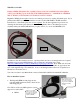
What Else is Needed? If using a MSD8 CD ignition box, a pullup resistor needs to be installed between the ignition (+12V) post and Mag + post on the side of the MSD8 ignition box! A minimum of a 900 Ohm min (to 1K max), .125 Watt min (to 2 Watt max) resistor is needed. BigStuff3’s ETM system requires, but does not include provisions for sensing driveshaft speed.
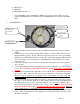
o MSD 7AL-2 o MSD 6AL o MSD Mag44 points box. Note: The ETM system, for BigStuff3’s GEN3 coil-on-plug systems (COP), does not require the ETM module, since all the necessary ETM hardware is resident in the GEN3 ECU. • The ETM Harness “3-Step Enable” wire Header connector goes to GEN3 Header marked ETM Ground wire 2-way drive shaft speed sensor connector DAE trigger wire o Connect the harness header connector into the GEN3 module header connector marked “ETM”.
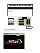
Use a Bosch style 30 Amp relay (part number 0332201107). Wire as follows: Pin 1 - Ground Pin 2 - Trans-brake signal Pin 3 - +12V Pin 4 - Timer Enable (Hdr. 1 Pin L2 or 4 way Boost connector pin A) Relay Trans Brake Signal text Timer Enable text Ground text +12V How to Configure the ETM System The ETM “Torque Management” configuration screens can be accessed from BigComm’s main tool bar as shown below. 5 Rev 1.
A user defined driveshaft speed is inputted into the GEN3’s “Desired Driveshaft Table”. The eight second (8) time period is broken up into 80 cells each representing 1/10 of a second. In each of the eighty (80) cells, the user can define the desired drive shaft speed. The desired driveshaft curve should be 100- 200 RPM above the “best” driveshaft curve possible. All the usual editing features are employed (Fill, Interpolate, etc…) in the table as well, but only a row at a time.
Torque Reduction Stage nine (9) means the GEN3 ECU will apply a very aggressive timing control strategy in an attempt to bring the actual drive shaft speed in line with the user defined, desired driveshaft speed. Note that the drive shaft “error” equals 896 RPM. A Torque Reduction Stage of twenty eight (28) means the GEN3 ECU will apply a minimally aggressive timing control strategy in an attempt to bring the actual drive shaft speed in line with the user defined, desired driveshaft speed.
The staged timing input section of this table is for the optional six or twelve shooter systems only. Checking this box activates the Traction Control system. 8 Rev 1.
Steps to Launching the Car with the 2 & 3 Step ETM After the burn-out, flip on the DAE/DLTRIGR switch (requires 12V to activate) used for the GEN3's data acquisition system. 12 Volts must be applied to this wire (the DAE/DLTRIGR switch must be turned on) for the 2-step & 3- step to work! Go to page 3 in this manual for more details. If you already have the DAE option, use it as usual.
The Initial Calibration (READ BEFORE USING THE SYSTEM): • • • • Make sure the driveshaft speed sensor is installed and functioning correctly. Disable the Torque Management system w/ ETM_Disable. Make sure the box titled “Torque Control Enable”, in the Torque Parameters table is not checked. See Torque Parameters screen print above. Following the “How to Use the ETM System procedure directly above, collect data from a pass.
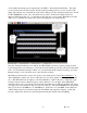
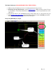
ETM or misfire control is on, since TOSS is greater than TISS Actual TOSS speed is above desired TISS curve TOSS is exceeding TISS (“A.K.A. driveshaft error”) so misfire is enabled and active Desired TISS speed curve 11 Rev 1.
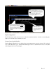
ETM (misfire) is off, since TOSS is below the user inputted TISS value Misfire counter starts at zero but increments every time a cylinder is misfired 12 Rev 1.
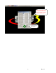
ETM Events A total of 47 misfire events occurred during the five (5) ETM events recorded. The Two-Step flag displays the state of either or both the 2 step and 3 step inputs in the Replay screen. Timer Enable on 2-Step on When 2-Step turns off, Timer Enable turns on Torque Reduction occurring 13 Rev 1.