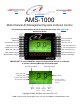
Next Back Click for Index. AMS-1000 Multi-Channel Air Management System for Boost Control The terminal pin descriptions may also be viewed on screen. See Page 24 of manual for details.
Next Back Click for Index. Notice: It is the responsibility of the purchaser to follow all guidelines and safety procedures supplied with this product and any other manufactures product used with the AMS-1000. It is also the responsibility of the purchaser to determine compatibility of the AMS-1000 with the vehicle and other components.
Next Back Click for Index. Description—The AMS-1000 multi-channel Air Management System represents the latest in Digital Technology. A Motorola 50-Mhz 16-bit processor is used to provide accurate and extremely fast control. A 128x64 pixel Graphical LCD Display is used to provide a Live display of Data and Inputs. GUI (Graphical User Interface) style operating system makes setup and programming more intuitive and user friendly.
Next Back Click for Index. Multiple control inputs, Launch, Shift, Scramble, and Reduce inputs. These control inputs can be configured through the Options menu to be Active with either a +12 volt or a Ground signal. Clutch Input—When active the Launch Target psi for each channel will be applied. The Launch Target psi can be set by the user through the Options Menu. When the Clutch Input is ON the Activation Signal is Ignored until the Launch signal is removed. i.e.
Next Back Click for Index. AMS-1000 Features: 1—Billet aluminum enclosure and all parts are specified over an extended temperature range. 2—Vibration and weather proof. 3—System software can be erased and reprogrammed by the factory for future software updates. 4—User settings will remain for up to 20 years with no power applied. No back up batteries are needed. 5—Factory default RESET available in the options menu to restore controller to state it was out of the box from the factory.
Next Back Click for Index.
Next Back Click for Index. Selecting MAP Sensor Connect the desired MAP sensor as outlined in the Installation section and then follow the instructions below. Warning—Make sure the Selected Sensor matches the one that is installed. All Sensors if connected will re-calibrate. If the wrong one is selected the pressure readings will NOT be correct! 1 2 3 Press the OPTION button. 4 Press the SENSOR button. 5 Select New Sensor. Press BOOST or AUX button to change MAP sensor type.
Next Back Click for Index. Setting Launch Psi, Boost and Aux Channels, Continued... 3 2 1 Press the LAUNCH button. Press the OPTION button. 4 Press BOOST or AUX button to adjust the Launch psi setting. 5 ESC, Exit and do NOT save new value Press the BACK button to exit. Use the BACK button to Return to the Main Screen. Adjust Value. SAVE, Exit and Save new value.
Next Back Click for Index. Setting Activation Hold and Clutch Reset Style The Activation Hold function when Programmed with a value greater than 0.00 will Delay the release of the Activation Input. i.e.—If the user is using a Wide Open Throttle switch to control the Activation. A Delay could be used to keep the system from re-setting if the throttle is lifted for a short period of time.
Next Back Click for Index. Turning the Aux channel On/OFF The Aux Channel can be used as a 2nd control channel or it can function as a Live Data readout and logging channel. If the Aux channel is ON (configured for control) the Display will show the actual psi value on the Aux channel. Note—This is the pressure on the control side. And the data log will represent the Actual target psi on the control side.
Next Back Click for Index. Setting Launch, Shift, Scramble, and Reduce polarity, Continued... 4 5 Press button to change Polarity Press the BACK button to exit. Use the BACK button to Return to the Main Screen. Press button to change Polarity Factory Reset option The Factory Reset option will return all controller settings to their factory defaults. Warning—All current settings will be lost if a Factory Reset is done! 1 3 2 Press the OPTION button. 4 Press the NEXT button three times.
Next Back Click for Index. Selecting Boost Channel Control Mode Multiple operating modes are available as outlined on Page 3. Time based, Shift based, and GPS (gear position sensor) based. Boost Channel Mode Note—GPS mode can only be selected using the Boost setup menu. When using GPS mode the Aux channel will be configured for GPS mode also. 1 Time based or Shift based modes can be used for the Boost and Aux channels. i.e.—Boost channel could be Time based and the Aux channel could be Shift based.
Next Back Click for Index. Boost Channel Setup Setting number of Control Stages, All Modes 1 2 Press the SETUP button. 3 Press the STAGE button. ESC, Exit and do NOT save new value Adjust Value. SAVE, Exit and Save new value. Setting Delay Timer, Shift Mode ONLY! 1 When in Shift Mode this setting will Delay the Activation or Boost Control until the Delay Timer has elapsed. i.e.—can be used to hold and/or delay the Launch psi while launching in 1st gear. 2 Press the DELAY button.
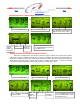
Next Back Click for Index. STAGE TIME IN SECONDS—Time Based mode ONLY!, This setting determines the Time for Each Stage when using Time Based mode. To determine the total time for all stages add the Time for each Stage together. Please see the example below for more details. 10 9 8 7 6 5 4 3 2 1 0 Target Psi Ramp2 Ramp3 Ramp4 Stage2 Timer Stage1 Timer .00 Ramp1 1.0 1.5 2.0 2.5 3.0 Real Time Activation 1 Stage4 Timer Stage3 Timer .5 Holds until Activation signal is removed.
Next Back Click for Index. TARGET PSI—All Modes, This setting determines the Target Psi for each stage. The range of Adjustment depends upon the MAP Sensor being used. The range is automatically scaled for current MAP sensor selected. The Target Psi can be increased or decreased for each stage. NOTE—It is possible to set a Target Psi value that can NOT be reached. This occurs when the Ramp Rate and/or Stage Time does not permit the full Target Psi setting to achieved. i.e.
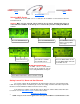
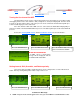
Next Back Click for Index. Viewing Graph of Boost channel Setup—The current boost channel setup can be viewed in graph form. Use the Arrow buttons to navigate through the setup. In Shift and GPS modes a .1 second time is added to the end of each stage (for viewing purposes only). If the Launch Psi setting is greater than 0 the user can include the Launch setting in the graph data. Without Launch Data. 1 2 Press the BOOST button. Press the VIEW button. Exit Navigate Data With Launch Data.
Next Back Click for Index. Selecting Aux Channel Control Mode Multiple operating modes are available as outlined on Page 3. Time based, Shift based, and GPS (gear position sensor) based. Only GPS mode will be available if the Boost channel is configured for GPS mode. If the Aux channel is OFF the following message will be displayed. Aux Channel Mode 1 2 Press the AUX button. A MAP sensor MUST be connected to the Aux channel to continue! See below. 3 Press the YES button to turn the Aux channel ON.
Next Back Click for Index. Viewing Logged Data The actual Target Boost Psi and Aux Target Psi is recorded (logged) for viewing and tuning purposes. Data logging will occur if the Data memory is erased and the Activation signal is present. Data logging will begin when a +12 volt signal is applied to the Activation Input. The Boost and Aux channels will record data for 35 seconds (less if the Activation signal is removed).
Back # Next Click for Index. Operating System Version and Error Codes The operating system can be updated by the factory. Use the instructions below to obtain the current Version Information. Any error that may occur will be stored as a number code and can be retrieved for diagnostics. Error codes can be erased after viewing. See below for details. System Version and Date. 1 2 Press the DATA button. No Error Codes Present. 3 Press the INFO button. Check for Error Codes. Error Codes Present.
Next Back Click for Index.
Next Back Click for Index.
Next Back Click for Index. Optional MAP Sensor Installation The optional sensor must be configured using the OPTION menu. See page 7 for details. To Solenoid and/or Manifold plumbing. 12223861 C B A +5V OUT GND Red MAP Sensor +5V Black White MAP Ground MAP Signal Signal to Boost or Aux channel as required. To Solenoid and/or Manifold plumbing. SSI 100 MAP Sensor +5V Red Black White MAP Ground MAP Signal Signal to Boost or Aux channel as required.
Next Back Click for Index. Specifications Normal Operating Voltage— 10 to 16 volts (Controller will function down to 7 volts, Solenoids need a minimum of 10 volts for proper operation). Maximum Current— 5 Amps for each Solenoid Output. MAP Sensor Input— 0 to 5 volts. GPS Input— 0 to 5 volts. Overall Height— .975” Overall Width— 2.850” Overall Length— 4.350” 3.850” 2.
Next Back Click for Index. Warranty Information NLR, LLC warrants to the original purchaser that the AMS-1000 Controller Shall be free from defects in parts and workmanship under normal use for 6 months from the date of purchase. NLR, LLC obligation under this warranty is limited to the repair or replacement of any component found to be defective when returned postpaid to NLR, LLC. The Controller must be returned with evidence of place and date of purchase or warranty will be void.
Next Back Click for Index. Quick Tech Tips: 1— If you are going to use the AMS-1000 in time based or shift input mode(not GPS) you will need to supply switched 12 volts to terminal number 1. This input will need to be turned on and off. Think of it like this, when the switch is off(not supplying 12 volts to terminal number 1) the AMS-1000 is in PROGRAM mode, allowing you to make changes to the program.