
Owner manual
20
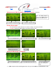
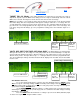
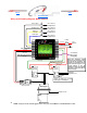
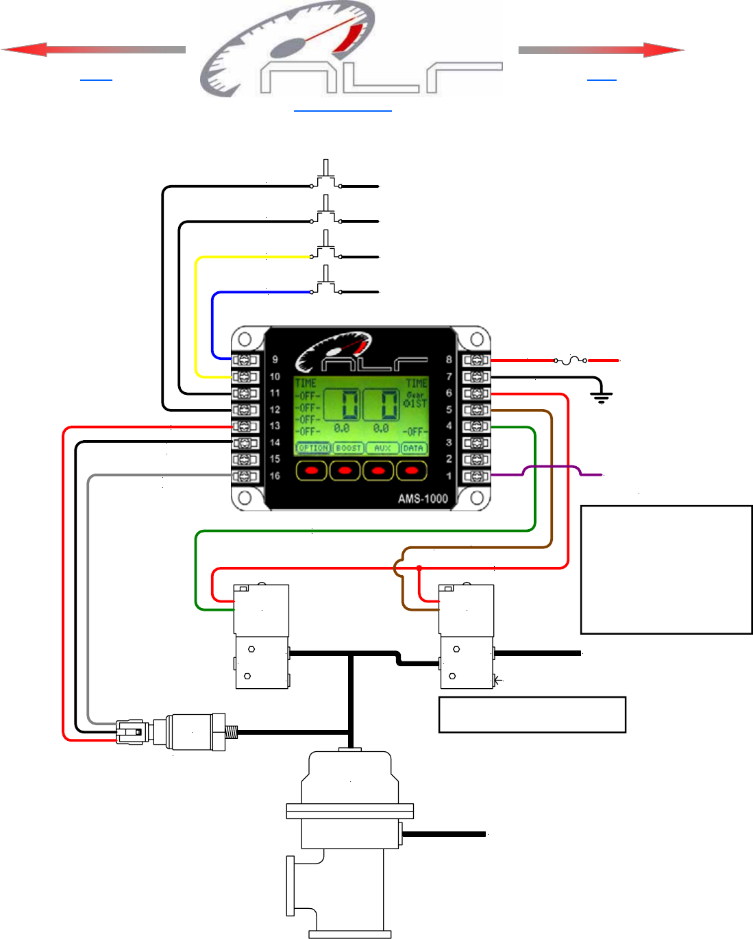
Wiring and Plumbing Diagram, Boost Channel
Click for Index.
Back
Next
Caution—Do NOT forget to install
1/8 NPT plug in the EXH port!
NOTE—Target Psi is the amount applied to the waste gate and is NOT the actual Manifold Boost Psi!
GROUND
10 Amp
Fuse
+12V
Switched
+12V or Ground
See Option Menu
Clutch Input
+12V or Ground
See Option Menu
+12V or Ground
See Option Menu
+12V or Ground
See Option Menu
Shift Input
Scramble Input
Reduce Input
MAP Sensor +5V
MAP Ground
MAP Signal, Boost Channel
OUT
EXH
IN
OUT
EXH
IN
Increase
Solenoid
Decrease
Solenoid
1/8 NPT
Plug
Air Supply or
Manifold Pressure
Solenoid +12V
Decrease Solenoid Ground
Increase Solenoid Ground
Wastegate
Manifold Pressure
+12V Activation
Signal or GPS
Sensor Voltage
Yellow, 20ga
Blue, 20ga
Red, 20ga
Black, 20ga
Gray, 20ga
Green, 20ga
Red, 20ga
Brown, 20ga
Black, 18ga
Purple, 20ga
Red, 20ga
SSI
60
Mount ON or as Close to
Gate as posible!
Note—The Activation signal
must be removed before turn-
ing off the unit for Data to be
stored to non-volatile memory.
If the Activation signal is con-
nected directly to the #8
Switched +12V Power terminal
the Data Log function will not
work correctly!