
User's Manual


4
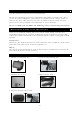
3. Mount
the license plate on
the license plate bracket.
4. Choose a routing path for the camera’s power cable through the vehicle’s body to the
reverse light circuit. If in doubt, se
ek professional installati
on assistance.
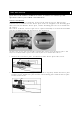
5. Some vehi
cles may have a hole available to pass the wire through, such as
where the
lic
ense plate light is mounted, or you can drill a hole close to where the powe
r cable
i
s attached to the camera. Once you have chosen where the cable will enter the
vehicle’s body, remove the camera. If you are able to use an existing opening,
skip
the next two steps.
6. Bef
ore you drill a hole you MUST CHECK and see WHAT IS BEHIND WHERE YOU ARE
DRILLING. If there are any vehicle components, such as electrical part
s or fuel
system com
ponents behind where you are drilling, you must take what
ever
precaution is necessary not to dam
age them. Remove the license plate and came
ra
before drilling.
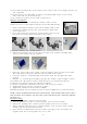
7. Af
ter you have drilled the hole, insert the supplied grommet, then pass th
e camera
cabl
es through the grommet into the vehicle. You must use the grom
met to prevent
the metal edge of the
hole from cutting the camera cable.
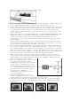
8. Next you’ll need to find the vehicle’s reverse lights. Turn the vehi
cle’s ignition key to
the accesso
ry position, engage the parking brake and put
the car in reverse. Look at
the ve
hicle’s tail lights to see where the reverse lights are located, they
are the white
lights. To locate the
reverse light’s 12 / 24 V+ wire it will be necessary to gain acce
ss
t
o the rear of the vehicle’s tail light. For help locating the vehicle’s reverse light circuit
contact your vehicle’s manufacturer for vehicle specific wiring di
agrams.
9. On
ce you have located the reverse light circuit you will have to route th
e camera
cabl
e to that location. You must securely fasten the power cable to prevent it
from
being caug
ht on any vehicle component such as the trunk hinge. Never route
the
cable on the outside of the
vehicle!
10. The reverse light sockets on most
vehicles
have two wires connected to them.
Usually the negative wire is black and the
positive wire is a colored wire. If
yo
u are
uncertai
n about the wiring, you can us
e a
12 / 24 volt multimeter available at most
auto parts stores to determine which
is
the posi
tive wire. Follow th
e
manufac
turer’s instructions for the
safe
use of the
multimeter.
11. After determining which wire is the
positive and which is t
he negative, turn
off the ignition key, then remove the battery’s negative ca
ble.
12. Splice t
he red wire using the supplied in-line wire connectors to the reverse light’s
positive (+) wire. Use a set of slip joint pliers to squeeze the TAP and insu
re good
connecti
on.