
Installation Guide
INSTALLATION
GUIDE
1
approx 60mm (2 3/8”) backset
2
3
5
HEAD JAMB
6
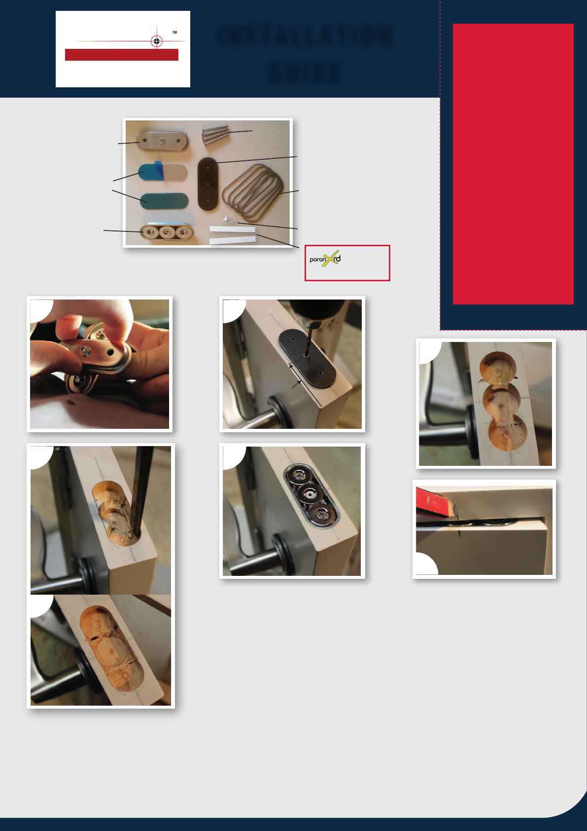
DOOR JAMB MAGNETIC ASSEMBLY
DRILLING TEMPLATE GUIDE
POWER ADJUSTMENT SPACER RINGS
(S/STEEL)
'DRILL IN' RUBBER BUFFERS AND
S/STEEL 10g FIXING SCREWS
SELF ADHESIVE S/STEEL COVER
PLATES
DOOR MAGNETIC ASSEMBLY
1. Remove magnetic assemblies from packaging. To separate assemblies twist apart sideways.
Keep magnetic assemblies at least 1 metre apart (and away from any steel objects) until secured
into door and jamb.
2. Measure and mark a centreline onto the top edge of the door. Measure and mark a backset of approx.
60mm (2 3/8") from the 'leading edge' of the door. Position the plastic DRILLING TEMPLATE GUIDE on the
top of door so the templates middle hole is lined up over the intersecting centreline and 'backset mark'.
Drill 3 x Ø3mm (1/8") pilot holes through the template into the centreline.
3. Using the Ø3mm (1/8") pilot holes as guides, drill 3 x Ø24mm (15/16") overlapping holes into the top of
door, to a depth of approx. 10mm (3/8"). (RECOMMENDED: FB-24 FORSTNER DRILL BIT- SOLD SEPARATELY).
4. Mark straight lines along the outer edges of the overlapping holes, then chisel where marked to create a straight sided recess. (4a)
5. Insert DOOR MAGNETIC ASSEMBLY into top of door and secure with 2 x screws provided.
Be careful not to over tighten screws as this may cause the flanged housing cups to deformand/or cracking in timber.
6. Close the door, then transfer the 'backset mark' up onto the head jamb.
4
4a
Precisi n
PLS24PRO-XHD
EXTRA HEAVY DUTY
CONCEALED MAGNETIC CATCH
Patent No. 568456
No. 8,864,188
FOAM STRIPS
(Sold separately)
WARNING use extreme
caution when handling
magnets as the attractant
forces are very powerful
and if allowed to snap
together violently, small
sharp chips can be thrown
off.
Do not attempt to remove
individual magnets from
assembly housing cups, as
this may result in magnet
breakage or personal
injury.