9.25, 9.25i Treadmill 9.25, 9.25i Treadmill Warning: This service manual is for use by Precor trained service providers only. If you are not a Precor Trained Servicer, you must not attempt to service any Precor Product; Call your dealer for service. This document contains information required to perform the majority of troubleshooting, and replacement procedures required to repair and maintain this product.
9.25, 9.25i Treadmill Section One - Things you Should Know About This Appendix Section One, Things You Should Know. This section includes technical specifications and a procedure matrix. Read this section, as well as the Treadmill Owner’s Manual, before you perform the maintenance procedures in this manual. Section Two, Software Features. Precor’s 9.25 and 9.25i Treadmill is programmed with several diagnostic and setup features.
9.25, 9.25i Treadmill Technical Specifications Physical Specifications Length: Width: Height: Running surface: Motor: Speed: Incline: Power: Weight: Shipping Weight: 67 inches (170 cm) 28.5 inches at handrails (71 cm) 25 inches at base (63.5 cm) 44 inches 51 inches by 17 inches (130 cm by 43 cm) 1.7 hp continuous duty 0.5 to 10 mph (0.
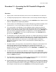
9.25, 9.25i Treadmill Procedure 2.1 - Accessing the 9.25 Treadmill's Diagnostic Program Procedure 1. Plug the power cord into the wall outlet, then turn on the treadmill with the circuit breaker. 2. The diagnostic program provide six different routines to aid it testing and trouble diagnosis. 3. With the PRECOR M9.25 banner scrolling, press and hold ENTER until the software version number is displayed in the right display windows. 4. The first routine is the LED display test.
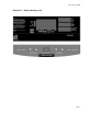
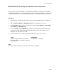
9.25, 9.25i Treadmill Diagram 2.1 - Display Housing, 9.
9.25, 9.25i Treadmill Procedure 2.2 - Accessing the 9.25i Treadmill's Diagnostic Program Procedure 1. Plug the power cord into the wall outlet, then turn on the treadmill with the circuit breaker. 2. The diagnostic program provide six different routines to aid it testing and trouble diagnosis. 3. For the purpose of accessing the various software routines, including the diagnostics program, the display housing keys are hypothetically numbered 1 to 7 from left to right. 4. With the PRECOR M9.
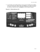
9.25, 9.25i Treadmill 11. The last routine is the circuit breaker trip test. This test checks the ability of the treadmill to trip the circuit breaker under software control. If the STOP key is pressed the trip signal will be sent to the circuit breaker and the circuit will trip, shutting off the treadmill. If you do not wish to trip the circuit breaker, press the ENTER key to exit the diagnostic program. Diagram 2.2 - Display Housing, 9.
9.25, 9.25i Treadmill Procedure 2.3 - Resetting All User Information This procedure completely resets the M9.25 user statistics. All previously-saved user information will be either reset to zero or changed to default values. All odometers will be reset to zero. If you want to save accumulated user information and odometer readings, record the information before performing this procedure. Note: This procedure is not available on the 9.25i. User stats must be reset individually per Procedure 2.4.
.25, 9.25i Treadmill Procedure 2.4 - Resetting an Individual User’s Information This procedure resets accumulated user information and odometer readings for an individual User ID. All previously-saved user information for a selected User ID will be either reset to zero or changed to default values. The odometer reading for the selected User ID will be reset to zero. Procedure 1. Plug the power cord into the wall outlet, then turn on the treadmill with the circuit breaker. 2. With the PRECOR M9.
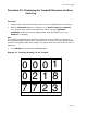
9.25, 9.25i Treadmill Procedure 2.5 - Displaying the Treadmill Odometer and Error Code Log Procedure 1. Plug the power cord into the wall outlet, then turn on the treadmill with the circuit breaker. 2. With the PRECOR M9.25 banner scrolling, press the ENTER, SPEED ▼ and SPEED ▲ keys, simultaneously. Continue to hold the keys until the message TREADMILL ODOMETER scrolls across the left display window. On 9.25i treadmills, press keys RESET,6,5, sequentially.
9.25, 9.25i Treadmill 4. Press ENTER. The error buffer is displayed and scrolls across the left display window (see Diagram 2.4). The most recent error condition will be displayed in position 1 and the oldest error will be displayed in position 5. When an error is added to a full log the new error will be inserted in position 1 and all other logs will be pushed down one position. The error that was in position 5 will be lost. 5.
9.25, 9.25i Treadmill Procedure 2.6 - Selecting United States Standard or Metric Units Selecting United States standard units causes data to be displayed in feet, miles and pounds. Metric data is displayed in meters, kilograms and kilometers. Procedure 1. Plug the power cord into the wall outlet, then turn on the treadmill with the circuit breaker. 2. Choose one: IF... You wish to verify the measurement standard the treadmill is currently using before you change the standard THEN...
9.25, 9.25i Treadmill 7. Use the SPEED ▲ or SPEED ▼ keys to select the alternate measurement standard. 8. Press ENTER twice to return to the User ID prompt.
9.25, 9.25i Treadmill Procedure 2.7 - Determining Software Version Numbers Software version numbers are invaluable for tracking and identifying problems and staying aware of changes to the operation and features of the product. Procedure 1. Plug the power cord into the wall outlet, then turn on the treadmill with the circuit breaker. 2. With the PRECOR M9.25 banner scrolling, press the ENTER key. On 9.25i treadmills, with the PRECOR M9.25 banner scrolling, press keys RESET,5,6,7,1, sequentially. 3.
9.25, 9.25i Treadmill Procedure 2.8 - Documenting Software Problems When a problem is found with either the software or upper or lower PCA’s, record the information listed below. If you isolated the problem to either the PROM, upper PCA, or lower PCA, include the information you recorded with the malfunctioning PROM or PCA when you ship it to Precor.
9.25, 9.25i Treadmill Section Three - Checking Treadmill Operation This section provides you with a quick method of checking treadmill operation. Check treadmill operation at the end of a maintenance procedure and when it is necessary to ensure that the treadmill is operating properly. Procedure 1. Plug the power cord into the wall outlet, then turn on the treadmill with the circuit breaker. 2. Place the treadmill in Manual Mode.
9.25, 9.25i Treadmill Procedure 4.1 - Calibrating the Lift System WARNING Always turn off the circuit breaker and unplug the treadmill before you remove the treadmill hood. Procedure 1. Remove the hood as described in Procedure 5.1 of the Residential Treadmill Service Manual. 2. Remove the lift motor from the treadmill as described in Procedure 6.4 of this appendix. 3. Place the treadmill upright. Lay the motor in front of the treadmill. 4. Plug the lift motor connector to the lower PCA.
9.25, 9.25i Treadmill Diagram 4.1 - Lift Motor Calibration Note: When you perform the next step, keep the white plastic nut in the same relative position to the drive screw. If necessary though, you may turn the drive screw 1/2 of a revolution. 12. Mount the lift motor on the treadmill as described in Procedure 6.4 of this appendix. 13. Check the operation of the treadmill as described in Section Three of this appendix.
9.25, 9.25i Treadmill Procedure 5.1 - Troubleshooting the Keypad and Upper PCA If the function keys on the electronic console are unresponsive, the problem may be either the upper PCA or keypad. This troubleshooting procedure gives you the information you need to determine which of these components is malfunctioning. Procedure 1. Set the circuit breaker in the “off” position.
9.25, 9.25i Treadmill Table 5.1 - Voltage Test Points (Function Keys Not Pressed) Place the positive lead of the voltmeter on... Pin 3 of J3 Pin 4 of J3 Pin 5 of J3 Pin 7 of J3 Pin 8 of J3 Pin 9 of J3 Pin 10 of J3 The voltmeter should read... 5 Vdc ± 500 mVdc 5 Vdc ± 500 mVdc 5 Vdc ± 500 mVdc 5 Vdc ± 500 mVdc 5 Vdc ± 500 mVdc 5 Vdc ± 500 mVdc 5 Vdc ± 500 mVdc Table 5.2 - Voltage Test Points (Function Keys Pressed) Place the positive voltmeter lead on...
9.25, 9.25i Treadmill Procedure 5.2 - Troubleshooting the Heart Rate System If the HEART RATE indicator does not blink with your heart beat when you perform Procedure 2.1, the problem may be either the heart rate receiver assembly or the chest strap assembly. This troubleshooting procedure gives you the information you need to determine which of these components is malfunctioning. Procedure 1.
9.25, 9.25i Treadmill 6. Hold the Heart Rate Test Transmitter (Precor part number 20045-101) near the display housing. If the HEART RATE indicator on the electronic console blinks with the LED on the Smart Rate Test Generator... THEN... The chest strap assembly is bad. Wear a new chest strap assembly when you use the Smart Rate System. 7. OTHERWISE... The heart rate receiver assembly is bad. Replace the heart rate receiver as described in Procedure 5.4 of the Residential Treadmill Service Manual.
9.25, 9.25i Treadmill Procedure 5.3 - Troubleshooting the Lift System System Description The lift system is powered by a 120 Vac lift motor that uses two independent motors windings, one operates the motor in an upward direction and one operates the motor in a downward direction. The motor contains a 10 KΩ or 1KΩ potentiometer (depending on manufacturer), driven by the motor, that indicates lift position. AC power to operate the lift motor is provided by a pair of triacs.
9.25, 9.25i Treadmill 8. Remove the P2 connector from the lower board. Using an ohmmeter, measure between terminals 1 and 3 of P2, between terminals 1 and 2 of P2 and between terminals 2 and 3 of P2. The measurements should be approximately 14.5Ω, 14.5Ω and 29Ω, respectively. If any of the measurements are significantly low, replace the lift motor. 9. Re-insert the P2 connector in the lower PCA. Set the treadmill circuit breaker in the “on” position.
9.25, 9.25i Treadmill Procedure 5.4 - Troubleshooting the External A.C. Power Source It is extremely important that any Precor treadmill be connected to and operated on a dedicated 20 amp A.C. circuit. A 20 amp dedicated circuit is defined as: a circuit fed by a 20 amp circuit breaker that feeds a single load. A treadmill operating from a non-dedicated circuit or a circuit breaker of less than 20 amps capacity will not have the necessary power available to operate normally under higher load conditions.
9.25, 9.25i Treadmill 2. The circuit breaker correctly feeds a single A.C. outlet but the neutral is common between several A.C. outlets. The common neutral lead must be removed from treadmill’s A.C. outlet and a new neutral lead from the treadmill’s A.C. outlet to the A.C. neutral distribution bar must be added. 3. Both the hot and neutral leads feed several A.C. outlets. Both the common neutral and hot leads must be removed from treadmill’s A.C.
9.25, 9.25i Treadmill Procedure 6.1 - Replacing the Fan WARNING Always turn off the circuit breaker and unplug the treadmill before you remove the treadmill hood. Removing and Replacing the Fan 1. Remove the hood. 2. Remove the fan from the motor shaft. 3. Push the new fan onto the motor shaft. If you are installing a new motor on the treadmill, push the fan onto the shaft of the new motor. 4. Replace the hood .
9.25, 9.25i Treadmill Procedure 6.2 - Replacing the Speed Sensor WARNING Always turn off the circuit breaker and unplug the treadmill before you remove the treadmill hood. Removing the Speed Sensor 1. Remove the hood. 2. Disconnect the speed sensor cable from the lower PCA. 3. Remove the nut that secures the speed sensor to the speed sensor bracket. Set aside the speed sensor. Replacing the Speed Sensor 4. Position the speed sensor next to the speed sensor bracket.
9.25, 9.25i Treadmill Procedure 6.3 - Replacing the Lift Platform WARNING Always turn off the circuit breaker and unplug the treadmill before you remove the treadmill hood. Removing the Lift Platform 1. Remove the hood. 2. Place the treadmill on its left side. Note: To avoid scratching or marring the treadmill, put a drop cloth underneath the treadmill when you perform Step 2. 3. Remove the e-rings and lift pins that secure the lift motor nut to the lift platform.
9.25, 9.25i Treadmill Procedure 6.4 - Replacing the Lift Motor WARNING Always turn off the circuit breaker and unplug the treadmill before you remove the treadmill hood. Removing the Lift Motor 1. Remove the hood. 2. Disconnect the lift motor wiring assembly from the lower PCA. 3. Remove the ground wire from the lift motor ground stud.
9.25, 9.25i Treadmill Procedure 6.5 - Replacing the PROM Anti-static kits (part number 20024-101) can be ordered from Precor. 1. The PROM and the associated printed circuit assembly (PCA) are static sensitive. Antistatic devices must be used and all anti-static precautions must be followed during this procedure. 2. Remove the printed circuit assembly per its associated procedure. 3. Currently we are using two styles of IC software packages.
9.25, 9.25i Treadmill Wiring Diagram 7.3 - 9.25, 9.
9.25, 9.25i Treadmill Block Diagram 7.4 - 9.25, 9.