PVS-15 Personal Viewing System Assembly and Operation Manual Cardio Theater Holdings, Inc. 21420-D NW Nicholas Court #12-13 Hillsboro, OR 97124 (800) 776-6695 (503) 645-8881 www.cardiotheater.
TABLE OF CONTENTS Parts List…………………………………...Page 2 Stand Assembly………………..………… Page 3-4 DVD Player Assembly………..…………..Page 5-7 LCD Screen Assembly………………..….Page 8-9 Mounting Screen Controller…………..….Page 10 Programming TV Channels………….…..Page 11 Cable Management……………………….Page 12 RF Distribution…………………………….Page 13 Specifications……………………………..
Parts List: Master Set Up Package 1 1 1 1 Master IR Remote Control Operations Manual Screen Controllers (1 for each Screen) Neoprene Mounting Pad (1 for each controller) DVD Player Master IR Remote (Optional) Screen Box 1 1 1 1 1 1 4 15 inch LCD Screen AC Adapter Adapter Power Cord LCD Back Cover Controller Cable LCD Screen Hardware Package Wire Ties Stand Box 2 1 1 1 1 1 8 Stand Feet Base Cross Bar Lower Vertical Tube Upper Vertical Tube (Short or Long Model) Base Cover Coax / Power Cable Hex Screws
Stand Assembly Step 2 Step 1 Determine width of stand feet in relation to the cardio equipment. Use a 7/16 wrench to secure 2 hex screws per leg. Insert lower vertical tube over center stub and hand install one 3/16 Allen head screw a few turns into vertical tube. Do not tighten at this time. (Clearance needed for Wires) Step 3 Step 4 Insert plastic base cover over lower vertical tube. Do not fasten down at this time. Insert upper curved tube into lower tube.
Stand assembly- continued Step 7 Step 8 Route coax and AC power plug to center Opening of base cover and make sure to tighten lower bolt before installing cover. With cables properly placed in cover slot, secure base cover with 2 Allen head screws provided. Step 9 Install last remaining Screw in upper tube Assembly and double-check all Fasteners for Tightness.
DVD Player Assembly NOTE: Skip to Page 7 if not installing DVD Player Important: There are two models of DVD brackets. Short DVD Bracket For S Model Stand Long DVD Bracket For L Model Stand 1: Run supplied Audio Video cable and DVD 12 Volt Power cable from opening at top of stand out through large round hole in upper tube of stand.
2: Pull Audio/Video and 12 Volt Power cable wires through hole in DVD bracket and attach bracket to stand with 2 hex screws provided. IMPORTANT: When attaching Short Version, confirm that the large square opening on the rear of the bracket is positioned on the right side of the stand tube as shown. Short Version Long Version 3: Plug Audio Video cable into the Video & Audio “Output” on the rear of the DVD player. 4: Plug 12 Volt Power cable into 12 Volt input on rear of DVD player.
6: Connect DVD 12 Volt Power cable to main Coax / Power wire coming through top of stand. 7: Connect the Video cable coming from the DVD player “Output” to the connector labeled “Video Y” on the back of the monitor and the cable going from the DVD players audio outputs to “Audio Left & Right” input on the back of the monitor.
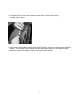
LCD Screen Assembly 1. Attach pivot assembly to back of LCD monitor using upper two mounting holes as shown in figure 1. Leave out the lower two mounting screws until after all wiring is installed onto back of monitor. 2. Install monitor assembly onto upper stand tube using (3) M4 X 10mm socket head cap screws as shown in Figure 2 3. Install power connector from harness that was installed into stand assembly earlier, to input on back of monitor labeled “DC12V” as shown in figure 3. 4.
LCD Screen Assembly (continued) 5. Remove slip-on antenna connector from monitor by pulling straight down on connection (Figure 5). Screw slip-on connector onto coax cable and then push assembly back into the monitor’s antenna connector. (Figure 6) 6. Attach Back Cover plate using 2 M4 x 10mm black screws. (Figure 7) Note: Before securing back cover, confirm that all cables connected to LCD screen have sufficient slack for tilting the monitor and are not that they are not intertwined.
Mounting Screen Controller CNTE-4 CNTE-16 1. Remove backing from neoprene mounting pad and place either vertically or horizontally around equipment handrail as appropriate as shown below. 2. Insert two nylon wire ties (provided) through the bottom holes in the mounting bracket on the rear of the Screen Controller. 3. Attach wire ties as tightly as possible around the horizontal or vertical bar so the controller can’t be rotated.
Auto Programming TV Channels The following requires the LCD Screen Master IR Remote Control Unit 1. 2. 3. 4. 5. Press menu button on Master IR Remote. Scroll Down to “Install” then press “Select”. Select “Auto Search” and press “Select”. Select Cable, HRC or Air (Check local cable company for HRC) Note: Programming may take up to 3 minutes. Manually Add or Erase Channels: 1. 2. 3. 4. 5. 6. Manually select channel using Master IR Remote. Press menu button on Master IR Remote.
Cable Management System The Optional Cable Management System is used to cover the antenna cable and power cords that run between the individual stands. It consists of a metal bracket that connects to the bottom of the monitor stand and a plastic two-channel extrusion that can be cut to length with common hand tools. 5 foot Cable Management extrusion.
RF Distribution Below is a diagram of a typical install. Please note that the tap values are dependant on having a 35 db signal at the output of the signal amplifier. It is best to use a quality amplifier that has a variable output so that you can adjust it to match 35 db even if your input is either lower or higher. These tap values and db readings are based on RF theory.
Specifications: 15” Color LCD Monitor Visible Screen Size Pixel Range Type Visual Angle Horizontal Frequency Vertical Frequency Display Color Input/Video Signal TV Color System Channel Memory Receiving Channel Video Input Color Power Adaptor Operating Temperature Conditions Humidity 304.1(H) X 228.1(V) 0.297(H) X 0.297(V) a-si TFT Liquid Crystal Display upper 55’/lower 65’, left 70’/right 70’ 31~60 KHz(Auto Set) 56~75 Hz(Auto Set) 16.2M Color Analog 0.
Warranty Cardio Theater™ warrants the Personal Viewing System to be free from defects in material and workmanship for the following period of time from date of shipment, provided that the products have not been subject to mechanical, electrical, or other abuse or modifications.
Technical Support Technical Support Numbers Telephone 1-800-776-6695 Technical Support Hours: 6:00 AM to 5:00 PM Monday through Friday PST. Write To: Cardio Theater Holdings, Inc. 21420-D NW Nicholas Court #12-13 Hillsboro, OR 97124 Notice Due to continuing advancements in technology, Cardio Theater Holdings, Inc. reserves the right to make changes in hardware, packaging, and any accompanying documentation without prior written notice.
17