
Installation Guide


PBS installation guide
Copyright © 2007 Precyse Technologies Inc. All rights reserved
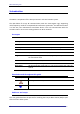
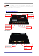
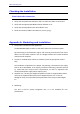
PBS - rear view
Connector /
indicator
Description
1. Power indicator
LED (red)
On - Power is connected.
Flashing - There is a problem with the power supply.
Off – power supply not connected.
2. Synch indicator
Synchronization LED (green)– Flashes once a second when
the system is active
3-6. PBS channel
indicators #1-4
Green LED (green) – flashes when a signal is sent on the
corresponding channel
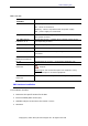
7. DC Power port
DC power port (12V-2 A, 24W MAX)
8. Heartbeat port
Not used at this stage
9-12. TCP\IP port 1-4
Network connector for corresponding channel. RJ45
connector.
13,16. RF Channel 1,4
antennae connectors
Physical antenna connector for the corresponding channel.
14, 15
RF transmit, RF receive – Connected to Amplifier unit.
17. External amplifier
connector
A DB9 connector that contains power and control
outputs.
Warning: Do not connect this port to a computer or any
other RS232 port or terminal equipment.
18. GPS Antenna
connector
Connect a GPS antenna (Either active or passive)
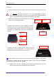
PBS hardware installation
Pre-installation checklist:
Determine the specific location for the PBS.
Ensure available power source (AC).
Available LAN port to connect to the iLocate ™ server.
Antennae.