
User's Manual


Precyse Technologies, Ltd..
Date: 7 November 2013 Page 9 of 12
Precyse Technologies
100 Ashford Center North
Suite 360
Atlanta, GA 30338
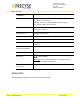
PBS - rear view
Connector /
indicator
Description
1. Power indicator
LED (red)
On - Power is connected.
Flashing - There is a problem with the power supply.
Off – power supply not connected.
2. Synch indicator
Synchronization LED (green)– Flashes once a second when
the system is active
3-6. PBS channel
indicators #1-4
Green LED (green) – flashes when a signal is sent on the
corresponding channel
7. DC Power port
DC power port (12V, 1A)
8. Heartbeat port
Not used at this stage
9-12. TCP\IP port 1-4
Network connector for corresponding channel. RJ45
connector.
13,16. RF Channel 1,4
antennae connectors
Disabled RF ports. These ports are disconnected internally.
14, 15
RF transmit, RF receive – Connected to Amplifier unit.
17. External amplifier
connector
A DB9 connector that contains DC voltage supply and
control outputs.
Warning: Do not connect this port to a computer or any
other RS232 terminal equipment.
18. GPS Antenna
connector
GPS input port. Connect the supplied GPS antenna.
Schematics
Will be provided on demand and under on-disclosure agreement.