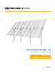
MULTI-POLE MOUNT - G2 ASSEMBLY INSTRUCTIONS step-by-step assembly and installation Version 1, Rev D SP3287-2 PCN 042412-1
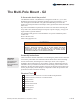
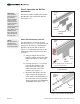
The Multi-Pole Mount - G2 A few words about the product The Multi-Pole Mount - G2 (MPM-G2) is designed to mount on 3, 4, or 6 inch SCH40/80 vertical steel pipe (installer supplied), and 4 x 4 inch square, or 5 x 4 inch rectangular horizontal tube. The goal of the MPM design is to limit the number of ground penetrations which helps reduce ground work and the associated labor costs.
9 8 7 6 5 4 10 11 Multi-Pole Mount - G2 Parts Identification 2 1 14 12 13 3 2 of 15 Assembly Instructions, Multi-Pole Mount - G2 (Version 1, Rev D)
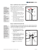
Step 1: Install Pipe Cap on Vertical Pipes CAUTION: Before assembly, be certain that the vertical pipe installation has met the project requirements and the concrete footings have fully cured. NOTE: For foundation and pipe recommendations, fill out the MPM RFQ form and email to: info@plpsolar.com Before installing Pipe Caps, verify that all Vertical Pipes are level to one another. Install one Pipe Cap on each Vertical Pipe.
Step 3: Assemble the Rail Set Assemblies CAUTION: Use care while working around the structure during assembly. There could be components that create hazards or obstruct free movement causing serious bodily injury. Many are at head/eye level. Move slowly and with care around the work area. NOTE: Be sure that the Rail Bracket is properly oriented to the Power Rail. Rail Set Assemblies include a Power Rail, Rail Bracket, and a Strongback Bracket (See Figure 3-1).
Align center of Power Rail to center of Rail Bracket 5/16” x 1” Carriage Bolts 5/16" Flange Nuts Center of Rail Bracket South Figure 3-4 Attaching Rail Bracket to Power Rail Attach the Strongback Bracket to the Rail Bracket Although the design of the Rail and Strongback Brackets allows for nine tilt angles accommodating seasonal tilt adjustments (10 through 55-degrees), for ease of assembly and safety, it’s recommended to set the tilt at 0-degrees during the assembly process.
Be certain to insert the 1/2" x 1-1/4" hex/lock bolt as shown in figure 3-4. If the hex/lock bolt is inserted from the opposite side, it will not secure the Rail Bracket to the Strongback Bracket creating an unstable rack. WARNING: The Rail Bracket must be secured to the Strongback Bracket using the hex/lock bolt as shown in figure 3-4. Failure to do so could lead to structural failure and or personal injury.
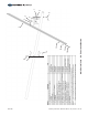
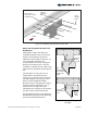
Step 4: Attaching the Rail Set Assemblies to the Horizontal Tube Each Rail Set Assembly is secured to the Horizontal Tube using two 1/2" L-Bolts and four Flange Nuts per Rail Set. Rail Set Assemblies are spaced along the Horizontal Tube in predetermined spans. The span between each is dependent on the size of Modules to be used. Follow the instructions below to measure and mark the locations of the Rail Set Assemblies on the Horizontal Tube.
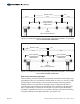
Module Length Module 1/2" Module 20% 20% Module 60% of Module Length between Rail Brackets 20% 20% Center (Run of Horizontal Tube) Figure 4-2: Establishing Position and Spacing of Rail Set Assemblies - for an install with an Odd number of Rail Sets 1/2" Module Length Module 60% of Module Length between Rail Brackets Module 20% 20% 60% of Module Length between Rail Brackets Center (Run of Horizontal Tube) Figure 4-3: Establishing Position and Spacing of Rail Set Assemblies - for an install
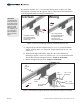
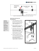
Shift the Rail Set Assembly to work around the Pipe Cap 60% of Module Length puts Rail Set on top of Pipe cap Pipe Cap Note: Power Rails not shown for clarity. Figure 4-4: Repositioning a Rail Set to work around a Pipe Cap Attaching the Rail Sets to the Horizontal Tube WARNING: This is a two person activity, because the Rail Set is unstable before it’s secured. One person should steady the Rail Set while the other secures it. Failure to do so could lead to serious personal injury. A.
Wrong Correct CAUTION: Be sure to tighten the L-Bolts evenly to close any gaps and keep the Rail Bracket tight against the Horizontal Pipe. Rail Bracket Rail Bracket L-Bolt No Gaps Visible Gaps Square Tube Note: Power Rail and Rail Bracket not shown for clarity. Figure 4-6: Alternate Tightening of L-Bolts to Close Gaps Step 5: Installing PV Modules to Power Rails with Module Clamps WARNING: This is a two person activity. Modules are heavy.
CORRECT WRONG Tabs Installed with Modules butted against Mid Clamp Tabs Mid Clamp is not square to Modules Visible Gaps between Mid Clamp Tabs and Modules Module Frames Figure 5-2: Correct and Wrong methods of installing a Mid Clamp Installing Modules using Standard End and Mid Clamps: Standard End Clamp Start with exterior Module and End Clamps. A. Place Module on two Power Rails, centering it lengthwise. Use a square to square-up the Module to the Power Rails. B.
Now install the next in-line Module using Mid Clamps. C. Before placing the interior Module onto the Power Rails, first insert two (one in each Power Rail channel) 5/16” x 2, 2-1/4, 2-1/2, or 2-3/4” carriage bolts (bolt length is dependent on depth of Module frame) into the Module Rail, sliding the bolts inward next to the previously installed exterior Module.
Installing Modules using RAD End and Mid Clamps: WARNING: Be certain that all Flange Nuts on End and Mid Clamps are tightened and torqued to the stated values. Failure to do so could lead to serious personal injury and/or damaged components and property. NOTE: RAD Bolts must be locked into the channel by rotating clockwise 90degrees. Use the indicator slot on the threaded end to identify whether or not the bolt has been locked.
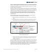
Step 6: Change the Tilt Angle of the Array WARNING: Do not attempt to remove the Pivot Bolt during tilt adjustments! Removal could lead to serious personal injury or death. Adjustments are made with the Pivot Bolt hardware loosened but in place. CAUTION: This is a two person activity. As the Pivot Bolt is loosened and the Support Bar hardware is removed, the rack is heavy and unstable.
WARNING: Do not attempt to remove the Pivot Bolt during tilt adjustments! Removal could lead to serious personal injury or death. Adjustments are made with the Pivot Bolt hardware loosened but in place. Loosen Pivot Bolt (DO NOT REMOVE) Remove 1/2” Lock Bolt and Washers Note: Modules not shown for clarity. Rotate Power Rail Retighten Pivot Bolt Reinstall 1/2” Lock Bolt and Washers Note: Rotated to a 40-degree tilt angle.