Universal Top-of-Pole Mount 8 Modules (UTPM8) Module Type G Assembly Instructions step-by-step assembly and installation SP3332-4
SAFETY CONSIDERATIONS This application procedure is not intended to supersede any company construction or safety standards. This procedure is offered only to illustrate safe application for the individual. FAILURE TO FOLLOW THESE PROCEDURES MAY RESULT IN PERSONAL INJURY OR DEATH. Do not modify this product under any circumstances, except where noted in this application procedure. This product is intended for use by trained technicians only.
Universal Top-of-Pole Mount For 8 Modules (UTPM8) For Module Type G WARNING Follow the procedures and precautions in these instructions carefully. About the product Periodic Inspection The UTPM8 for module Type G is designed for a wide range of 60 cell Module sizes, from 37-42” in width to 61-67” in length. The Universal Top-of-Pole support structure mounts on 8 inch SCH40/80 galvanized steel pipe (installer sup-plied).
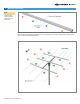
UTPM8 Type G Main Components Strongback Module Rails Support Bar Double Hole Slide Clamp Mounting Sleeve Cross-Bars Single Hole Slide Clamp There are seven main components and attaching hardware.
Universally adjustable to accommodate a range of PV Module sizes E-W adjustability of Module Rails along Cross-Bars. N-S adjustability of Single & Double Hole Slide Clamps along Module Rails.
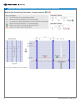
1 Calculate Site Specific Dimensions NOTE When selecting mounting holes, make certain that the hole diameters accept 1/4” hardware as it will be used to secure the PV Modules to the system. The dimensions must be taken from the site-specific Modules. The dimensions will be used to calculate the Module Rail positions. 2 Calculate and Mark the Rail Positions on the Cross-Bars Use the worksheet on the next page to calculate Rail positions on the Cross-Bars.
2 6 Calculate and Mark the Rail Positions on the Cross-Bars (continued) Assembly Instructions, UTPM8 Type G
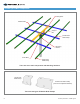
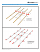
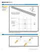
3 Mark the Cross-Bars NOTE Use precision when measuring and marking the Rail positions on the Cross-Bars. Measure and mark the center of the Cross-Bars then use the calculated dimensions I and O from the previous page to mark off their respective Rail positions. The image below shows these marks and their relationship to the Cross-Bars and Rails after assembly.
4 Mark the Double Hole Slide Plate Positions on the Rails NOTE Use precision when measuring and marking the Double Hole Slide Plate positions on the Module Rails. Locate the center of the Rails and mark as shown above. These marks are for the four (one-per Rail) Double Hole Slide Plates only. The additional Slide Plates do not require marks as they will be aligned to the Module mounting holes as the Modules are installed.
6 Attach Double Hole Slide Plates to Rails On each of the four Rails, install the Double Hole Slide Plates to be centered over the previously made marks on the Rails. Insert the head of the Hex Bolt into the Rail channel as shown and align their centers over the marks. Tighten these four Slide Plates securely and torque at 32-34 ft.-lbs.
8 Install the Mounting Sleeve on Vertical Pipe N Slip the Mounting Sleeve on top of the Mounting Pole allowing it to slide down and bottom out on the Pole. Rotate the Mounting Sleeve so that the Support Bar 9 Pivot Tab is pointing north and the Strongback Vertical Towers are leaning south. Tighten Set Bolts and torque to 55-60 ft-lbs. Install the Strongback CAUTION This is a two person activity.
9 Install the Strongback (continued) Tighten Pivot Bolt closing any visible gaps between the Strongback and the Mounting Sleeve Towers. Torque to 125-150 ft.-lbs. 10 Install the Cross-Bars CAUTION This is a two person activity. Cross-Bars are long and unstable before they are fully secured to the Strongback. Cross-Bars must be held in place by one person while the second person aligns and secures them to the Strongback. Failure to do so could lead to serious personal injury.
11 Install Rails CAUTION This is a two person activity. Module Rails are unstable before they are secured to the Rail Brackets. When installing the Rails orient their profiles as shown. Be sure to align the correct side of the Rail with the Rail alignment marks on the Cross-Bars. Align the Rail to the alignment marks and straddle its mounting holes over the Cross-Bar. Secure with 3/8” x 2” x 2-5/8” U-Bolt, Flat Washers, Lock Washers and 12 Hex Nuts at each Cross-Bar.
12 Install Modules CAUTION This is a two person activity. Modules are heavy and unstable before they are fully secured to the Module Rails. PV Modules must be held in place by one person while the second person aligns and secures them to the Module Rails. Failure to do so could lead to serious personal injury and damaged components. Align Module mounting holes with the installed Double Hole Slide Plates and secure Module with 1/4” x 3/4” Hex Bolt, Flat Washers, Lock Washer and Hex Nut.
13 Square and Align the Array. Return and Tighten Mounting Hardware CAUTION Be certain to retighten all Module Rail and PV Module mounting hardware and torque to the specified values. Failure to do so could lead to structural failure, damaged components and/or serious personal injury. 14 Using a square and visual references, ensure that the array is aligned to the mounting structure. Confirm that the PV Modules are square and have consistent even spaces all around. Adjust if necessary.
15 Adjust the Array Tilt Angle (continued) C. Re-tighten the Pivot Bolt. The Pivot Bolt cannot be left loose - the Mounting Sleeve Vertical Towers must be firmly clamped to the sides of the Strongback eliminating any gaps between the Vertical Assembly Instructions, UTPM8 Type G Towers and the Strongback. Torque to 125-150 ft.-lbs.
Global Headquarters 660 Beta Drive Mayfield Village, OH 44143 Telephone: 440.461.5200 Fax: 440.442.8816 preformed.com info@plpsolar.