
User Manual

14
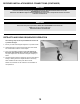
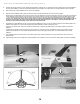
*Apply blue thread locker*
Wing Installation
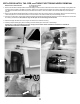
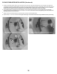
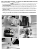
Apply a small bead of CA to the outer edge of the plywood rib located in the fuselage wing pocket. Note, CA accelerant may be used to
expedite curing time. DO NOT CONTINUE UNTIL CA is fully CURED.
Locate the four carbon fiber wing tubes. Using a short tube on each side of the fuselage near the leading edge and a long tube on
each side of the fuselage near the trailing edge of the wing, test fit each wing tube, ensuring the tubes pass beyond the internal
plywood supports. Please note, you may lightly bevel the end of the wing tubes on the side that will be inserted into the fuselage using
220 grit sandpaper, to allow the wing tubes to pass through the plywood supports easier.
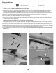
Orient the servos toward the bottom of the fuselage and slide the left and right wing panels half-way onto the fuselage.
Connect the aileron servo lead to its respective extension in the fuselage.
Fully seat the wing panels into the fuselage, while being careful to align the wing mounting tab with the slot in the fuselage. Be sure to
avoid pinching wires during this process.
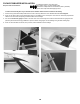
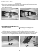
Using a #1 phillips screwdriver, secure each wing panel to the fuselage with a M3x10 phillips head self-tapping screw. Avoid over-
tightening the screw, and do NOT use blue thread locker on this connection.
Once satisfied with the fit, glue the wing tubes into the wings for additional strength. Use 15-minute epoxy, to secure the wing tubes to
the wing. Use isopropyl alcohol and a paper towel to wipe away any excess epoxy to ensure a flush fit.
Power on the radio system. Check the aileron trim by comparing the trailing edge of the aileron relative to the trailing edge of the wing.
If adjustment is needed, remove the clevis from the control horn, and turn the clevis. Re-attach the clevis to the control horn and inspect
the mechanical trim of the aileron. Repeat this step until the aileron is flush with the trailing edge of the wing.
Once satisfied with the mechanical trim of the aileron, apply a drop of blue thread locker at the point where the clevis and control
linkage meet.
1.
2.
3.
5.
7.
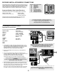
Required Tools and Fasteners:
#1 Phillips Screwdriver
Blue Thread Locker
(2) M3x10 Phillips Head Self-Tapping Screws
4.
6.
8.
Thin CA
15 minute epoxy
CA accelerant (Optional)
9.