INSTALLATION INSTRUCTIONS PCM-MS2 Universal Flat Panel Mount NORTH AMERICA 3130 East Miraloma Avenue Anaheim, CA 92806 USA USA and Canada – Phone: 800-368-9700 Fax: 800-832-4888 Other Locations – Phone: (001)-714-632-7100; Fax: (001)-714-632-1044 ©Premier Mounts 2009 9531-000-501-04 EUROPE Swallow House, Shilton Industrial Estate, Shilton, Coventry, England CV79JY Phone: +44 (0) 2476 614700 Fax: +44 (0) 2476 614710
PCM-MS2 Table of Contents Warning Statements ........................................................................................................................................- 2 Parts List ...........................................................................................................................................................- 3 Installation Tools (not supplied) .....................................................................................................................
PCM-MS2 Parts List This wall mount is shipped with all proper installation hardware and components. Make sure that none of these parts are missing and/or damaged before beginning installation. If there are parts missing and/or damaged, please stop the installation and contact Premier Mounts (800) 368-9700.
PCM-MS2 Hardware Pack M4 x 30 ( Qty 6) M5 x 30 ( Qty 6) M4 x 25 ( Qty 6) M5 x 25 ( Qty 6) M4 x 16 ( Qty 6) M5 x 16 ( Qty 6) M6 x 45 ( Qty 6) M8 x 70 ( Qty 4) M6 x 30 ( Qty 6) M6 x 25 ( Qty 6) M8 x 45 ( Qty 6) M6 x 16 ( Qty 6) M8 x 30 ( Qty 6) M8 x 25 ( Qty 6) M8 x 16 ( Qty 6) Universal Spacers (Qty 24) Installation Manual Page - 4 -
PCM-MS2 Thread Depth Indicator Step 1. Insert the thread depth indicator (supplied) through the thread inserts found on the back of the flat panel to make sure the inserts measure the same full depth and mark it. Step 2. Locate the correct diameter screw for the thread insert. Compare your marking to the screws (supplied). Step 3. If your selected screw is longer than the marking on the thread depth indicator, DO NOT USE this screw. Step 4. The screw length must not bypass the marking.
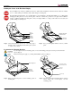
PCM-MS2 Finding the Center of the Flat Panel Display Proper installation procedure by qualified personnel as outlined in the installation instructions must be adhered to. Failure to do so could result in personal injury and possible damage to the flat panel. Invert the flat panel and place it on a soft, flat surface to prevent damage to the flat panel. Failure to do so will result in damaging the flat panel. Do not lay the flat panel on the floor without any protection to the glass.
PCM-MS2 CL Bottom of Flat Panel Align the Mounting Brackets Mounting Bracket Inverted Flat Panel Center of Viewing Guide Center Line Step 3. Match the center of viewing guide with the center line you marked in step 1. Griplate™ Installation Dimples The mounting brackets are designed with a center viewing guide on the side to indicate the center of the bracket. Griplates™ have M4, M5 M6 and M8 hole patterns to fit the hardware that your flat panel requires.
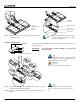
PCM-MS2 SN AP Wall Plate End Covers Installation Step 1. Place the upper and lower wall plates on a flat surface. Step 2. Align the wall plate end cover with the wall plate center rods (see illustration above). Step 3. Attach the wall plate end cover to the upper and lower wall plates and press down firmly. When the two engage, an audible ‘snap’ will be heard. Step 4. Repeat step 3 to attach the other wall plate cover to the opposite side.
PCM-MS2 16" Step 5. Level the wall plate with the reference arrow pointing up to the ceiling. Step 6. Drill eight (8) ¼" pilot holes to the marked wall. Step 7. Secure the upper and lower wall plates using the eight (8) 5/16" lag bolts and flat washers. Do NOT over-tighten lag bolts when attaching the mount to the wall. Improper installation may result in personal injury or damage to property.
PCM-MS2 Securing the Flat Panel to the Wall Mount AT LEAST (2) PEOPLE ARE STRONGLY RECOMMENDED TO LIFT AND SECURE THE FLAT PANEL TO THE WALL PLATE. FAILURE TO DO SO COULD RESULT IN SERIOUS INJURY AND POSSIBLE DAMAGE TO THE FLAT PANEL. Step 1.
PCM-MS2 Lateral Shift Adjustment LATERAL SHIFT Step 1. Make any lateral shift adjustment and lock it by tightening the two (2) M6 x 30mm (supplied) to the bottom of the mounting brackets. Installing the Safety Knurl Knobs Step 1. Tilt the flat panel and secure the two (2) M6 x 12 mm) safety knobs to each of the mounting brackets.
PCM-MS2 Technical Specifications All measurements are in inches(mm).
PCM-MS2 Warranty PREMIER MOUNTS LIMITED LIFETIME WARRANTY What and Who is Covered by this Limited Warranty and for How Long Premier Mounts warrants this product to be free from defects in material and workmanship for the lifetime of the original owner of this product. The limited warranty is valid only for the original purchaser of the product. What Premier Mounts Will Do At the sole option of Premier Mounts, Premier Mounts will repair or replace any product or product part that is defective.